Cold area house with passive energy-saving ventilation system

A ventilation system, a passive technology, applied in ventilation systems, residential buildings, space heating and ventilation, etc., can solve problems such as poor air quality, affecting human health, etc., to improve combustion efficiency, eliminate harmful gases, and prevent pollution Effect

Inactive Publication Date: 2013-03-20
HARBIN INST OF TECH
View PDF4 Cites 3 Cited by
  • Summary
  • Abstract
  • Description
  • Claims
  • Application Information

AI Technical Summary

Problems solved by technology

[0003] In order to solve the problem that the doors and windows are closed in order to ensure the indoor temperature in houses in cold areas, the present invention leads to poor indoor air quality and affects human health, and further proposes a cold area house with a passive energy-saving ventilation system

Method used


Image

  • Cold area house with passive energy-saving ventilation system
  • Cold area house with passive energy-saving ventilation system

Examples


specific Embodiment approach 1

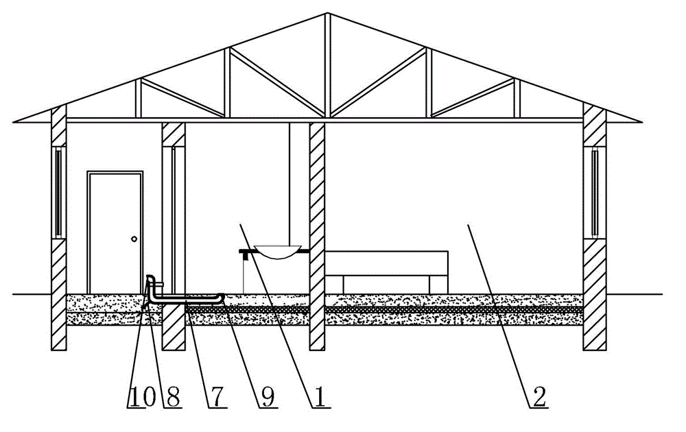
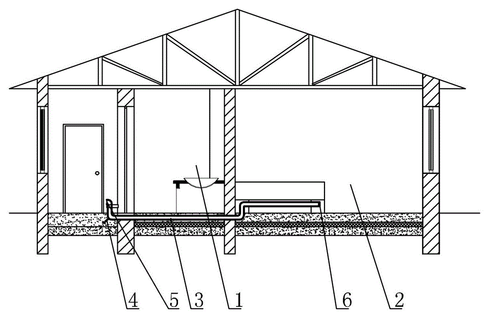
[0007] Specific implementation mode one: combine figure 1 Describe this embodiment, a cold area house with a passive energy-saving ventilation system described in this embodiment includes a house main body, the house body includes a kitchen 1 and a bedroom 2, this embodiment also includes a passive ventilation system for a bedroom, and the bedroom is passively ventilated The system includes a first ventilation pipe 3 and a first air outlet pipe 4. The first ventilation pipe 3 is buried in the ground in the main body of the house, and the first ventilation pipe 3 is located on the ground insulation layer. The first air inlet 5 on the door bucket wall in the main body communicates, the other end of the first ventilation pipe 3 communicates with the first air outlet 6 located on the lower surface of the Kang Kang in the bedroom 2, and the first air outlet pipe 4 communicates with the first ventilation pipe. 3 connected, and the first air outlet pipe 4 is located in the sand cushi...

specific Embodiment approach 2

[0008] Specific implementation mode two: combination figure 1 To illustrate this embodiment, a house in a cold region with a passive energy-saving ventilation system described in this embodiment has louver valves installed at 5 places of the first air inlet, and louver valves are installed at 6 places of the first air outlet.

[0009] The technical effect of this embodiment is: the louver valve can adjust the air intake volume of the first air inlet 6 and the first air outlet 6 at any time, and then adjust the fresh air volume and temperature in the bedroom.

[0010] Other components and connections are the same as those in the first embodiment.

specific Embodiment approach 3

[0011] Specific implementation mode three: combination figure 1 To illustrate this embodiment, the diameter of the first ventilation pipe 3 of a house in a cold area with a passive energy-saving ventilation system described in this embodiment is 5cm-20cm, and the distance between the first air inlet 5 and the ground is 25cm-30cm. Other components and connections are the same as those in the first embodiment.


PUM


Abstract

The invention relates to a cold area house, in particular to a cold area house with a passive energy-saving ventilation system. The problems that the air quality is relatively poor and the health of a human body is affected when a door and a window are closed for keeping indoor temperature in the cold area house are solved. The cold area house comprises a house body and a passive ventilation system of a bedroom, wherein the house body comprises a kitchen and the bedroom; the passive ventilation system of the bedroom comprises a first ventilating pipe and a first air outlet pipe; the first ventilating pipe is buried in the ground in the house body and is positioned on a ground heat-preserving layer; one end of the first ventilating pipe is communicated with a first air inlet in a door bucket wall of the house body; the other end of the first ventilating pipe is communicated with a first air outlet in the lower surface of a hanging ondol in the bedroom; and the first air outlet pipe is communicated with the first ventilating pipe and is positioned in a sand cushion layer of the ground of a door bucket. The cold area house is applied to the field of buildings.

Description

technical field [0001] The invention relates to a residence in a cold region, in particular to a residence in a cold region with a passive energy-saving ventilation system. Background technique [0002] Indoor air pollution caused by rural cooking has become one of the main causes of harm to people's health in rural areas. The World Health Organization pointed out in the "2002 World Health Report" that "in terms of disease burden, indoor smog released from solid fuels is one of the top ten major risk factors in the world." Studies have shown that in developing countries, acute upper respiratory tract infection is closely related to indoor air pollution. The total time of combustion activities in rural residences is relatively long, and most of them use primitive stoves such as traditional wood stoves, coal stoves, and kangs, which cannot maintain long-lasting good combustion conditions. When the oxygen around the kitchen stove is insufficient, the fuel in the stove will bur...

Claims


Application Information

Patent Timeline
Patent Type & Authority Applications(China)
IPC IPC(8): E04H1/02F24F7/04
Inventor 金虹凌薇
Owner HARBIN INST OF TECH
Why Eureka
Try Eureka