Wind power conversion mechanism and high altitude wind power generator

A conversion mechanism and wind energy technology, applied in wind power generation, wind generator components, wind engines, etc., can solve the problems of weak ability to adapt to changes in wind direction, low power transmission efficiency, and collision of kites, so as to achieve stable adaptation to changes in wind direction, Effect of improving energy conversion rate and high power transmission efficiency

Active Publication Date: 2013-03-20
CHINA NAT COAL GROUP CORP
View PDF7 Cites 4 Cited by
  • Summary
  • Abstract
  • Description
  • Claims
  • Application Information

AI Technical Summary

Problems solved by technology

[0003] Traditional wind power generation is greatly affected by factors such as site, wind direction, and wind speed, and has many disadvantages: first, wind farms are often relatively large in scale, and ground wind turbines are used, which need to occupy a large amount of land; The environment has a certain negative impact; in addition, wind turbines need to be supported by high towers to enter a height of several hundred feet above the ground, and the wind at this height is relatively small and unstable, and it is difficult to align with the wind direction at any time. The actual conversion rate Low, and the manufacturing cost and construction cost of conventional wind turbines are high
[0009] First, the cables of the two kites are directly wound on the coaxial reels installed side by side. If the distance between the cables is too close, the kites will collide with each other during the movement, which is easy to be damaged, and the phenomenon of cable entanglement is very easy to occur. If it is entangled, the whole set of equipment will ...

Method used


Image

  • Wind power conversion mechanism and high altitude wind power generator
  • Wind power conversion mechanism and high altitude wind power generator
  • Wind power conversion mechanism and high altitude wind power generator

Examples


Embodiment Construction

[0040] In order to enable those skilled in the art to better understand the solution of the present invention, the present invention will be further described in detail below in conjunction with the accompanying drawings and specific embodiments.

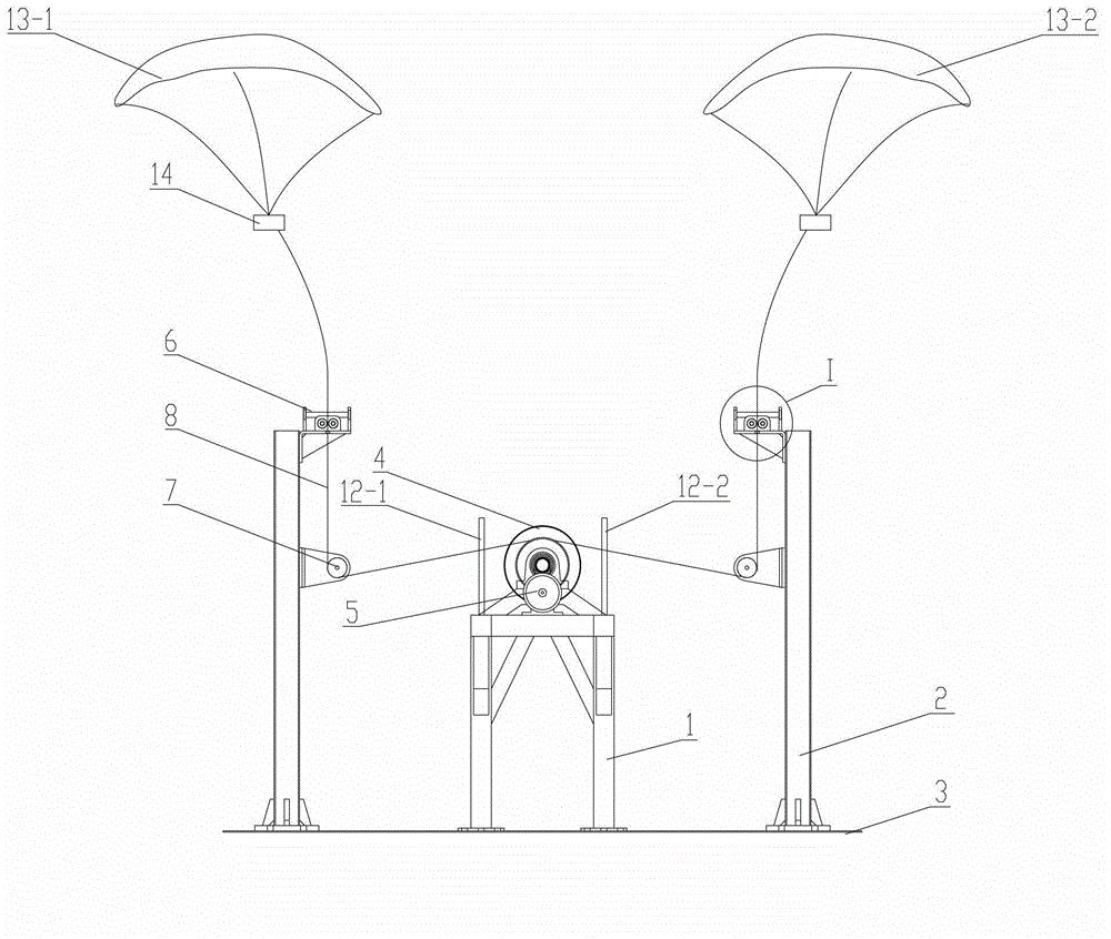
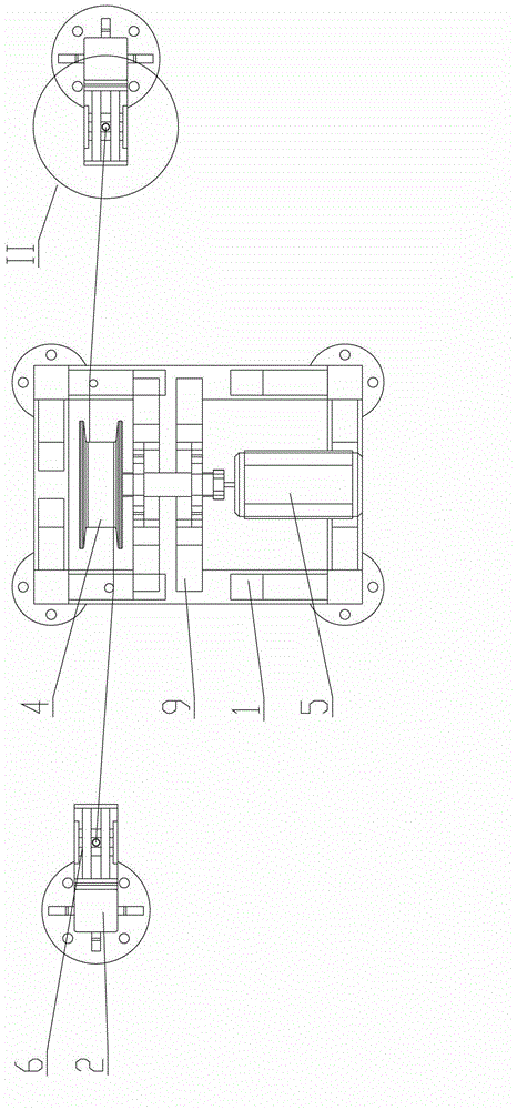
[0041] Please refer to figure 1 , figure 2 , figure 1 It is a structural schematic diagram of a specific embodiment of the wind energy conversion mechanism provided by the present invention; figure 2 for figure 1 A top view of the wind energy conversion mechanism shown.

[0042] As shown in the figure, in the first specific embodiment, the main components of the wind energy conversion mechanism provided by the present invention are the drive frame 1 and the rope guide frames 2 on both sides, and the drive frame 1 is welded into a rectangular shape with a certain height by profile The bottom of the frame is fixed on the foundation 3 through a flange, the top is equipped with a bidirectional reciprocating wheel 4 and a generator...


PUM


Abstract

The invention discloses a wind power conversion mechanism. The wind power conversion mechanism comprises reciprocating wheels, a power generator, universal rope guiding mechanisms and traction cables, wherein the power generator is driven by the reciprocating wheels to generate electricity; the universal rope guiding mechanisms are arranged at two sides of the reciprocating wheels; and the traction cables are wound on the reciprocating wheels and are used for connecting with two ends of an aircraft to respectively wind the universal rope guiding mechanism at the corresponding side. The mechanism is compact in structure and stale in performance, can effectively avoid cable winding and can adapt to various wind directions, so that the wind power conversion efficiency can be obviously improved. The invention further discloses a high altitude wind power generator with the wind power conversion mechanism.

Description

technical field [0001] The invention relates to the technical field of wind power generation, in particular to a mechanism for converting kinetic energy generated by light aircraft such as kites or parachutes flying at high altitudes into electric energy. The invention also relates to a high-altitude wind power generation device equipped with the wind energy conversion mechanism. Background technique [0002] At present, wind energy has gradually developed into a major alternative energy source and has been promoted globally. [0003] Traditional wind power generation is greatly affected by factors such as site, wind direction, and wind speed, and has many disadvantages: first, wind farms are often relatively large in scale, and ground wind turbines are used, which need to occupy a large amount of land; The environment has a certain negative impact; in addition, wind turbines need to be supported by high towers to enter a height of several hundred feet above the ground, and...

Claims


Application Information

Patent Timeline
IPC IPC(8): F03D5/00F03D9/00F03D11/00
CPCY02E10/722Y02E10/70Y02E10/72
Inventor 张阳
Owner CHINA NAT COAL GROUP CORP
Why Eureka
Try Eureka