

Dual-swing omni-directional moving spherical robot
A spherical robot, all-round technology, applied in the direction of motor vehicles, transportation and packaging, etc., can solve the problems of restricting the popularization and application of spherical robots, difficult control, and difficult engineering realization, so as to improve the use value, expand the scope of application, and facilitate The effect of control
- Summary
- Abstract
- Description
- Claims
- Application Information
AI Technical Summary
Problems solved by technology
Method used
Image

Examples
Embodiment 1
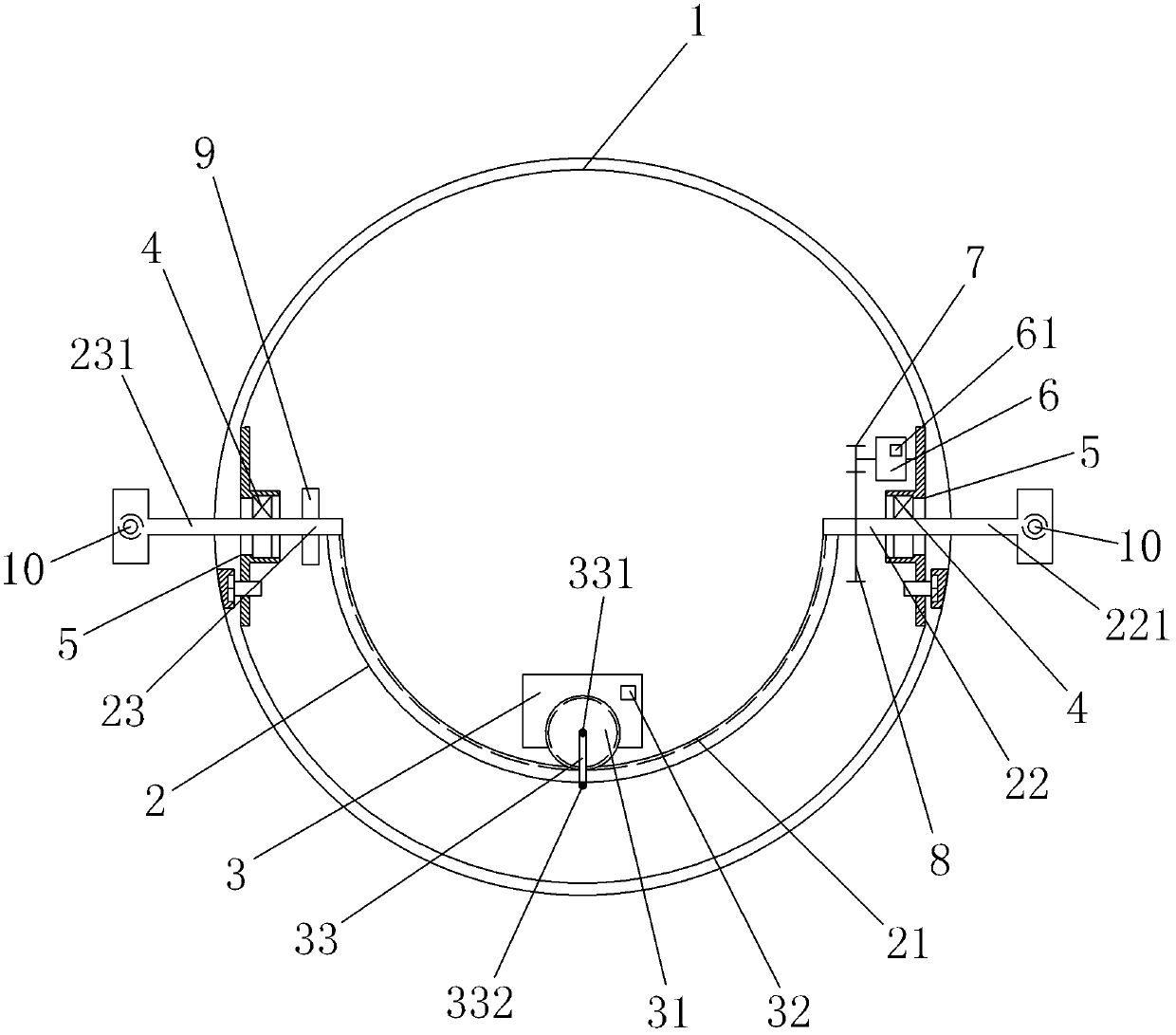
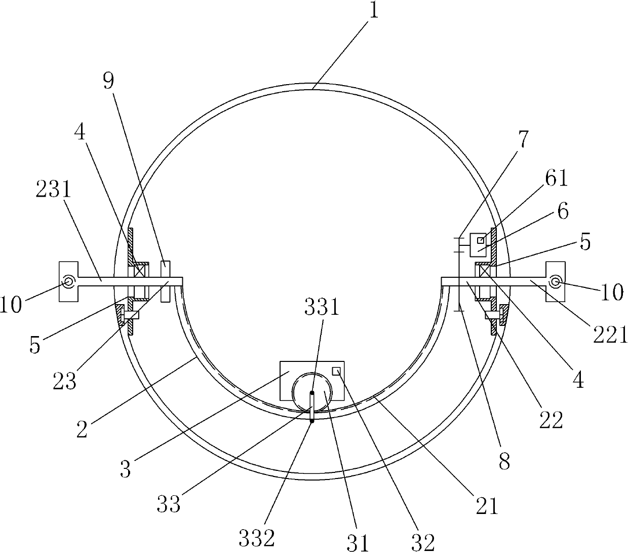
[0039] Such as figure 1 As shown, a double-swing omni-directional motion spherical robot includes a spherical shell 1 and a walking transmission mechanism located inside the spherical shell 1; the walking transmission mechanism includes a semi-circular ring 2 and a mass trolley 3 driven by an internal motor, so The opening of the semi-circular ring 2 is upward, and the semi-circular ring 2 remains vertical; the inner surface of the semi-circular ring 2 is provided with gear teeth 21, and the quality trolley 3 is provided with a driving gear 31, which is connected to the driving gear 31. The gear teeth 21 provided on the inner surface of the semi-circular ring 2 are mated together; the quality trolley 3 is provided with a Bluetooth receiving control device 32 for driving and controlling the rotation of the driving gear 31 provided on the quality trolley 3 .
[0040] The two ends of the semi-circular ring 2 are provided with two supporting short shafts 22, 23 protruding outwards...
Embodiment 2
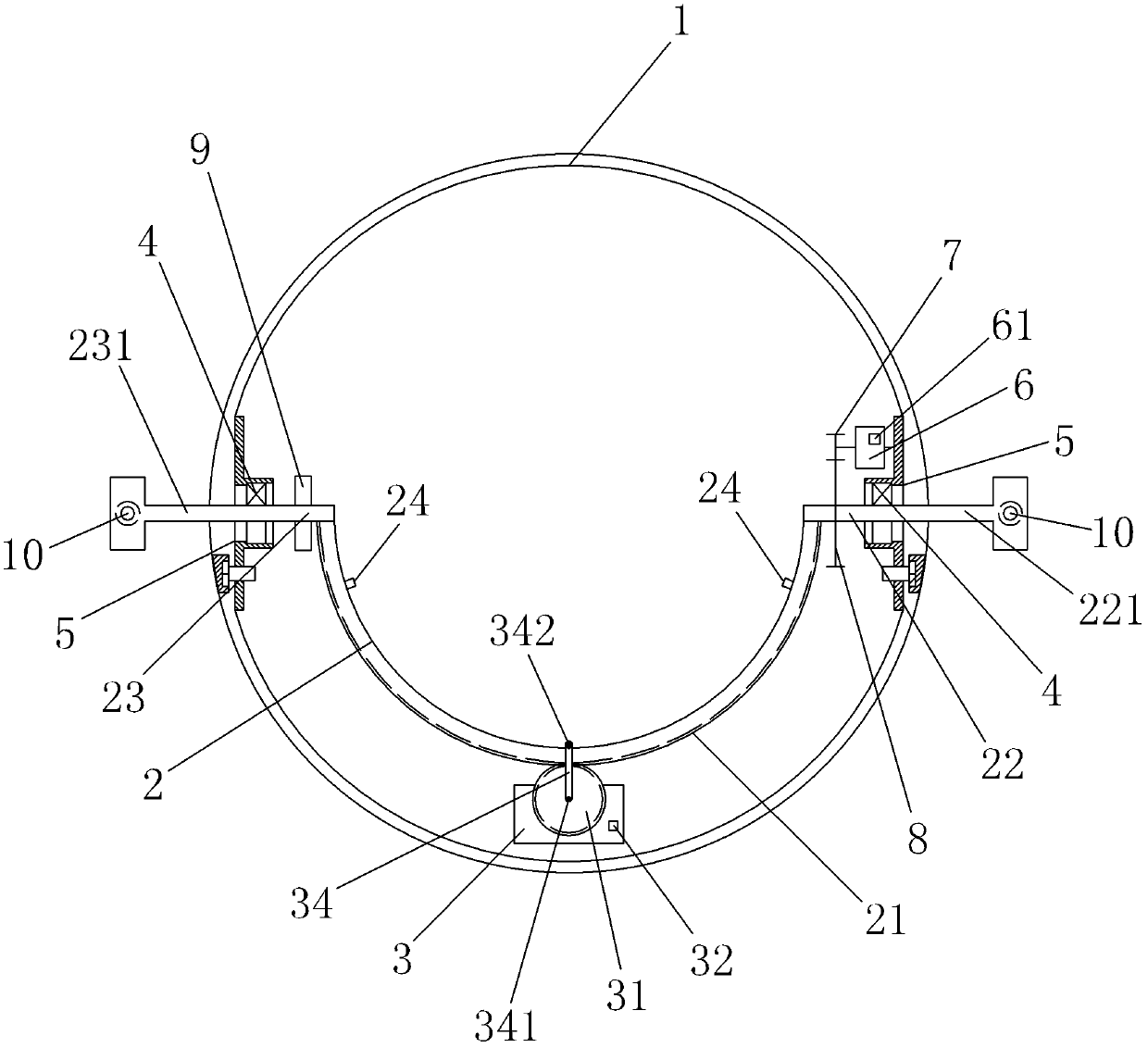
[0050] Such as figure 2 As shown, the difference between this embodiment and Embodiment 1 is that: the outer surface of the semi-circular ring 2 is provided with gear teeth 21, the quality trolley 3 is provided with a driving gear 31, and the driving gear 31 is provided with a preventive gear. The fixer 34 that the mass trolley 3 falls off from the semicircular ring, one end 341 of the fixer 34 is rotatably installed on the drive gear 31; the other end 342 is sleeved on the semicircular ring 2 through a bearing, and is connected with the The inner side of the semicircular ring 2 constitutes a rolling pair; the driving gear 31 and the gear teeth 21 on the outer surface of the semicircular ring 2 are mated together; and the two ends of the semicircular ring 2 are provided with The limiting block 24 of dolly 3 strokes.
PUM
 Abstract
Description
Claims
Application Information