Device capable of realizing continuous constant flow pumping of concrete and control method of device

A constant flow, concrete technology, which is applied to components of pumping devices for elastic fluids, pump control, fluid pressure actuators, etc., can solve the problem of concrete backflow, unstable pumping flow, and inability to achieve constant flow pumping and other problems, to achieve the effect of eliminating shock vibration and constant concrete pumping volume

Inactive Publication Date: 2013-03-20
CHANGAN UNIV
View PDF8 Cites 16 Cited by
  • Summary
  • Abstract
  • Description
  • Claims
  • Application Information

AI Technical Summary

Problems solved by technology

However, there are some obvious defects in the implementation of this technology: when the left and right pumping systems are in the pumping condition at the same time, the oil pump supplies oil to the two main oil cylinders at the same time, and the hydraulic oil will only enter the system with a small load. If the external load of the pumping system is different, the phenomenon that the pumping system cannot be moved in place may occur, resulting in the failure of the whole device to work normally.
In addition, this technology does not take measures to prevent backflow. During the movement of the distribution valve, the outlet of the Y-shaped pump in a high-pressure state communicates with the hopper in a low-pressure state, which may easily cause concrete backflow.
This technology has the problem of unstable pumping flow, cannot achieve constant flow pumping, and cannot completely solve the problem of shock vibration

Method used


Image

  • Device capable of realizing continuous constant flow pumping of concrete and control method of device
  • Device capable of realizing continuous constant flow pumping of concrete and control method of device
  • Device capable of realizing continuous constant flow pumping of concrete and control method of device

Examples


Embodiment 1

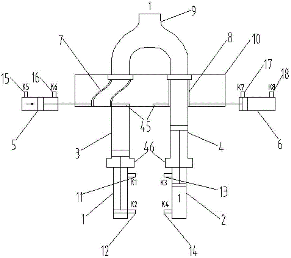
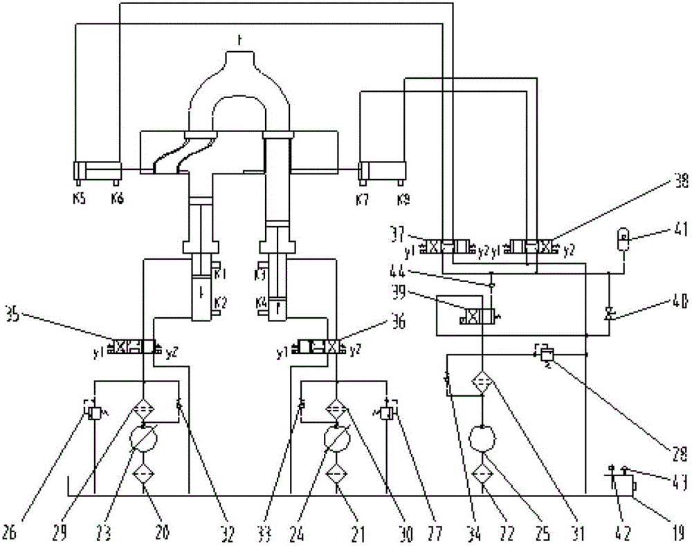
[0097] Such as Figure 5 to Figure 12 Shown is a schematic diagram of the working process of the continuous constant flow pumping system based on the S-shaped valve. Start working position with the left pumping cylinder 3 starting to suck material. The left distributing valve oil cylinder 5 is in the left position, the left pumping cylinder 3 communicates with the hopper 10, the left main oil cylinder 1 has a rod cavity to feed oil, and the left pumping system is in the suction working condition. After the ts2 acceleration time, the left pumping system enters a period of t2 constant speed suction process, when the K2 travel switch 12 of the left main cylinder 1 is triggered, the left pumping system starts to end the suction working condition, and ends after the ts1 deceleration time Suction. In order to ensure that the suction is completely completed, wait for tw1 time after ts1. After the time tw1 ends, the rodless chamber of the left distributing valve oil cylinder 5 ente...

Embodiment 2

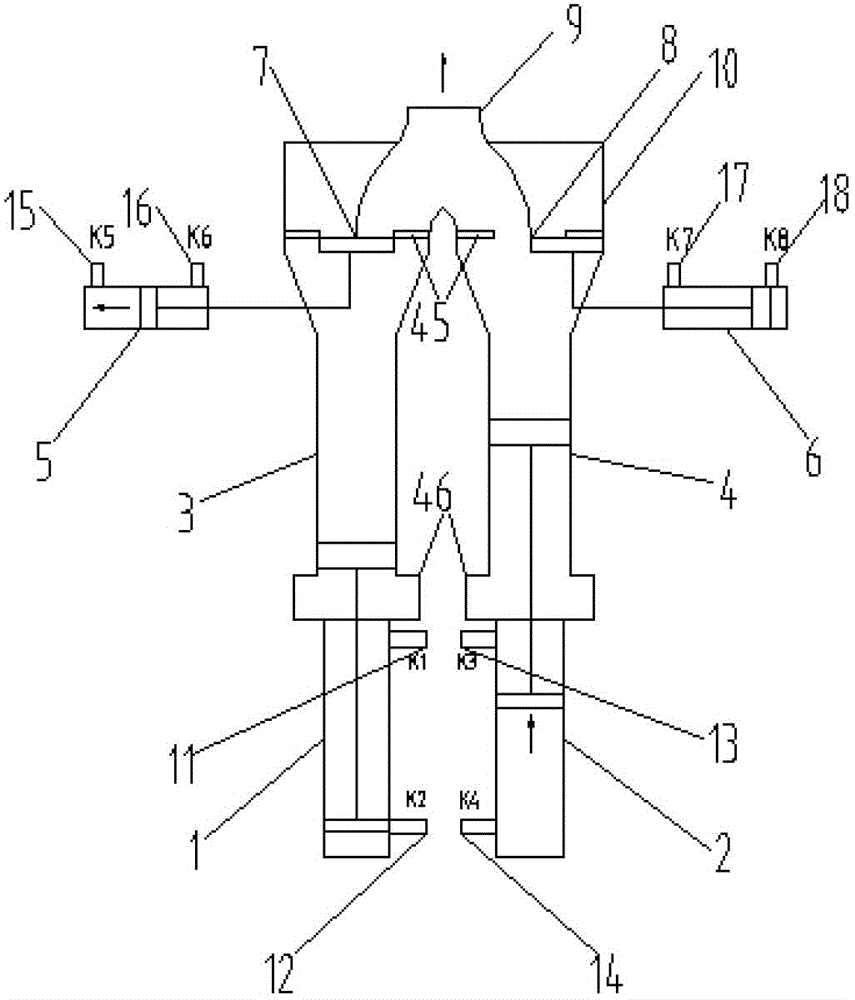
[0099] Such as Figure 14 to Figure 21 Shown is a schematic diagram of the working process of the continuous constant flow pumping system based on the gate valve. The working principle and process of the continuous pumping device using gate valves are basically the same as those using S-shaped valves. Start with the left pumping cylinder 3 starting to suck material. The left distributing valve oil cylinder 5 is in the right position, the left pumping cylinder 3 communicates with the hopper 10, the left main oil cylinder 1 has a rod cavity to feed oil, and the left pumping system is in the suction working condition. After the ts2 acceleration time, the left pumping system enters a period of t2 constant speed suction process, when the K2 travel switch 12 of the left main cylinder 1 is triggered, the left pumping system starts to end the suction working condition, and after the ts1 deceleration time, the suction ends material. In order to ensure that the suction is completely ...


PUM


Abstract

The invention mainly aims at providing a device capable of realizing the continuous constant flow pumping of concrete and a control method of the device, wherein one sides opposite to one ends of a left distribution valve and a right distribution valve near a left pumping cylinder and a right pumping cylinder are respectively provided with baffle plates for preventing concrete backflow, a controller is respectively connected with a left pumping system and a right pumping system and is also connected with a system start and stop electromagnetic directional valve, a display is connected with the controller, and the pumping-out stroke time T1 of the pumping system is equal to the sum of the speed reduction time tp of the pumping-out stroke completion of the other pumping system, the material suction stroke time T2, the twice moving time 2t3 of the distribution valves, the three-times waiting time tw1+tw2+tw3 and the acceleration time tp of the pumping-out stroke starting. The device and the method have the advantages that the continuous uninterrupted and constant flow pumping can be realized, a Y-shaped pump outlet in a high pressure state and a hopper in a low pressure state always maintain separated and disconnected through the baffle plates, and the concrete backflow phenomenon cannot occur.

Description

technical field [0001] The invention belongs to the field of engineering machinery, and relates to a device capable of realizing continuous constant flow pumping of concrete and a control method thereof. Background technique [0002] In recent years, concrete pumps have been more and more widely used in infrastructure construction. Most of the current concrete pumps use a double-cylinder pumping method. While one pumping cylinder is in the pumping stroke, the other pumping cylinder is in the suction stroke. Since the rod cavity (or rodless cavity) of the left and right pumping main cylinders is connected, the pistons of the left and right pumping cylinders reach the limit position at the same time, and then the distribution valve cylinder controls the action of the distribution valve. After the distribution valve moves in place, the left and right pumping main The oil inlet and outlet of the oil cylinder are exchanged to realize the alternate cycle pumping of the two pumpin...

Claims


Application Information

Patent Timeline
Patent Type & Authority Applications(China)
IPC IPC(8): F04B15/02F04B53/10F04B49/00F15B1/02F15B13/044F15B21/04
Inventor 张志友王欣朱文锋赵冠雄
Owner CHANGAN UNIV
Why Eureka
Try Eureka