
Control valve block special for tractor hydraulic suspension

A technology of hydraulic suspension and control valve, applied in mechanical equipment, fluid pressure actuating device, servo motor components, etc., can solve the problems of messy installation, hydraulic control oil circuit affecting the accuracy of control action, work reliability, complex structure, etc. To achieve the effect of convenient electronic control, improve work reliability and control flexibility, and simple structure

Active Publication Date: 2015-05-06
SHANDONG HONGYU AGRI MACHINERY
View PDF4 Cites 0 Cited by
  • Summary
  • Abstract
  • Description
  • Claims
  • Application Information

AI Technical Summary

Problems solved by technology

If various control valve parts are used to assemble, not only the structure is complicated and the installation is messy, but also the accuracy of the control action and the reliability of the work will be affected due to the long hydraulic control oil circuit.
At present, the assembly structure has been adopted internationally for this valve group, but it is still not an integral structure formed by an integral valve body.

Method used


Image

  • Control valve block special for tractor hydraulic suspension
  • Control valve block special for tractor hydraulic suspension
  • Control valve block special for tractor hydraulic suspension

Examples


Embodiment Construction

[0032] The principles and features of the present invention are described below in conjunction with the accompanying drawings, and the examples given are only used to explain the present invention, and are not intended to limit the scope of the present invention.

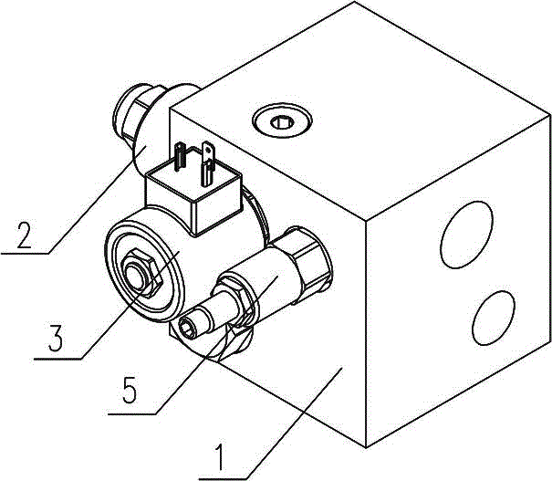
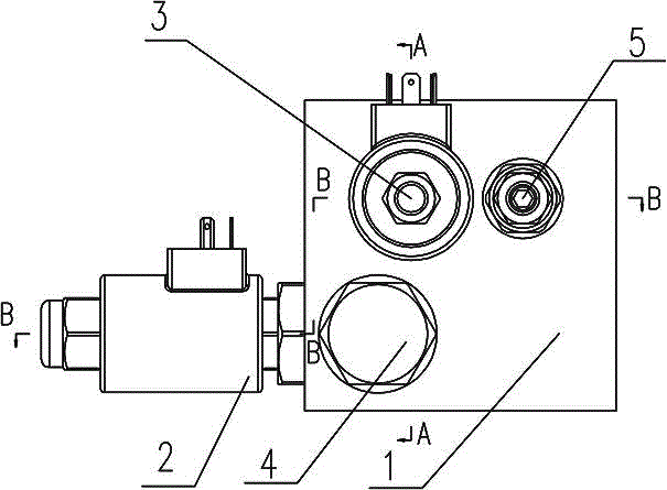
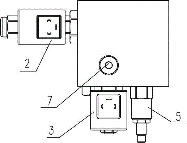
[0033] Such as Figure 1 to Figure 9 As shown, a special control valve block for tractor hydraulic suspension, including a valve body 1 and an electromagnetic proportional lifting control valve 2 inserted in the valve body 1, an electromagnetic proportional lowering control valve 3, a check valve 4 and a safety valve 5 , the outline of the valve body 1 is in the shape of a cuboid, the left side of the valve body 1 is inserted with the electromagnetic proportional lift control valve 2, the left side of the valve body 1 is provided with an oil outlet C, the The front side of the valve body 1 is inserted with the electromagnetic proportional drop control valve 3, the one-way valve 4 and the safety valve 5. The right si...


PUM


Abstract

The invention discloses a control valve block special for tractor hydraulic suspension. The control valve block special for tractor hydraulic suspension comprises a valve body, an electromagnetic proportional increase control valve, an electromagnetic proportional decrease control valve, a check valve and a safety valve, wherein the electromagnetic proportional increase control valve, the electromagnetic proportional decrease control valve, the check valve and the safety valve are installed inside the valve body in an inserted mode. The outline of the valve body is of a cuboid shape, the electromagnetic proportional increase control valve is installed on the left side surface of the valve body in an inserted mode, an oil outlet is installed on the left side surface of the valve body, and the electromagnetic proportional decrease control valve, the check valve and the safety valve are installed on the front surface of the valve body in an inserted mode. An oil inlet and an oil return port are installed on the right side surface of the valve body, oil ducts communicated with all valve part oil ways are installed inside the valve body, and the electromagnetic proportional increase control valve, the electromagnetic proportional decrease control valve, the check valve, the safety valve and the oil ducts constitute the control valve block special for tractor hydraulic suspension. The control valve block special for tractor hydraulic suspension has the advantages of being concise in structure, facilitating electronic control, and facilitating connection with an external oil way and a hydraulic cylinder. Compared with a bulk hydraulic control valve, work reliability and control flexibility can be improved.

Description

technical field [0001] The invention relates to an electronically controlled hydraulic suspension system for a tractor, in particular to a special control valve block for a tractor hydraulic suspension. Background technique [0002] At present, most of the various tractors manufactured in China belong to the mechanical control mode: that is, the working state of the hydraulic distributor is changed through the control handle and the control mechanism connected to it, so that the lifter can be lifted or lowered, and then the lifter is moved through a complex mechanical linkage. The displacement and resistance changes are fed back to the distributor to control it, so as to achieve the purpose of making the lifter automatically return to the neutral position and stop moving. This kind of mechanically controlled lifter has low precision, complicated structure, relatively difficult manipulation, easy wear and deformation, and low service life. With the improvement of econom...

Claims


Application Information

Patent Timeline
Patent Type & Authority Patents(China)
IPC IPC(8): F15B13/02
Inventor 曹健姜洪兴王松浩刘健波王袆博
Owner SHANDONG HONGYU AGRI MACHINERY
Learn More