Heat-dissipation structure of light-emitting diode (LED) daylight lamp

A technology of LED fluorescent lamp and heat dissipation structure, which is applied in the field of lighting, can solve the problems such as the difficulty of formulating LED fluorescent lamp standards, the difficulty of ensuring the safety of actual use, and the difficulty of ensuring safety, so as to avoid electric shock, meet the temperature requirements, and reduce the area.

Inactive Publication Date: 2013-03-20
黄嘉宾
View PDF12 Cites 11 Cited by
  • Summary
  • Abstract
  • Description
  • Claims
  • Application Information

AI Technical Summary

Problems solved by technology

[0002] In order to solve the heat dissipation problem of the lamp beads, the existing LED fluorescent lamps mostly use aluminum substrates as the lamp board material plus a half-plastic half-aluminum lamp tube cover or a half-plastic half-fan-shaped radiator lamp tube cover, which plays a greater role in the LED lamp beads. Good heat dissipation, but the aluminum substrate has a large area, high cost, and exposed metal. For LED fluorescent lamps that use voltages above 36v, electric shocks

Method used


Image

  • Heat-dissipation structure of light-emitting diode (LED) daylight lamp
  • Heat-dissipation structure of light-emitting diode (LED) daylight lamp
  • Heat-dissipation structure of light-emitting diode (LED) daylight lamp

Examples


Embodiment 1

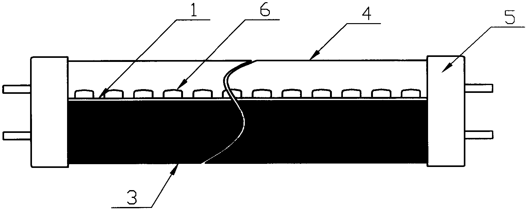
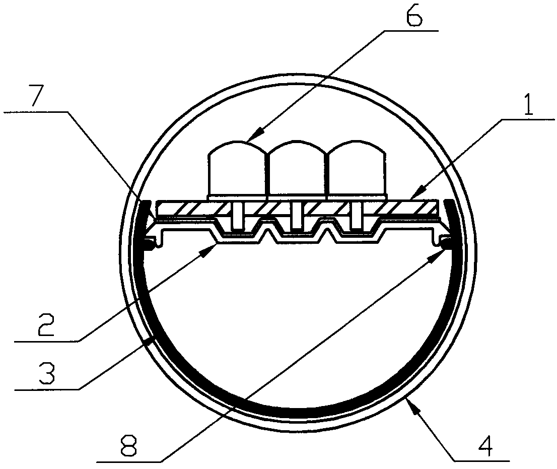
[0036] Such as figure 1 , figure 2 As shown, the present invention is composed of an LED lamp board 1, a lamp bead heat conducting plate 2, a metal heat dissipation inner sleeve 3, a lamp tube outer cover 4, and a plug 5. The lamp beads 6 are welded on the lamp board 1, and the metal heat dissipation inner sleeve 3 is an opening The two inner sides of the metal heat dissipation inner sleeve 3 are respectively provided with convex strips 8, the outer diameter of the arc of the metal heat dissipation inner sleeve 3 is the inner diameter of the lamp tube outer cover 4, and the LED lamp board 1 is connected with the heat-conducting silica gel 7. The lamp bead heat conduction plate 2 is fixedly connected and placed on the convex strip 8 provided by the metal heat dissipation inner sleeve 3. The two sides of the lamp bead heat conduction plate 2 are attached to the two inner sides of the metal heat dissipation inner sleeve 3 and placed together inside the lamp tube outer cover 4 C...

Embodiment 2

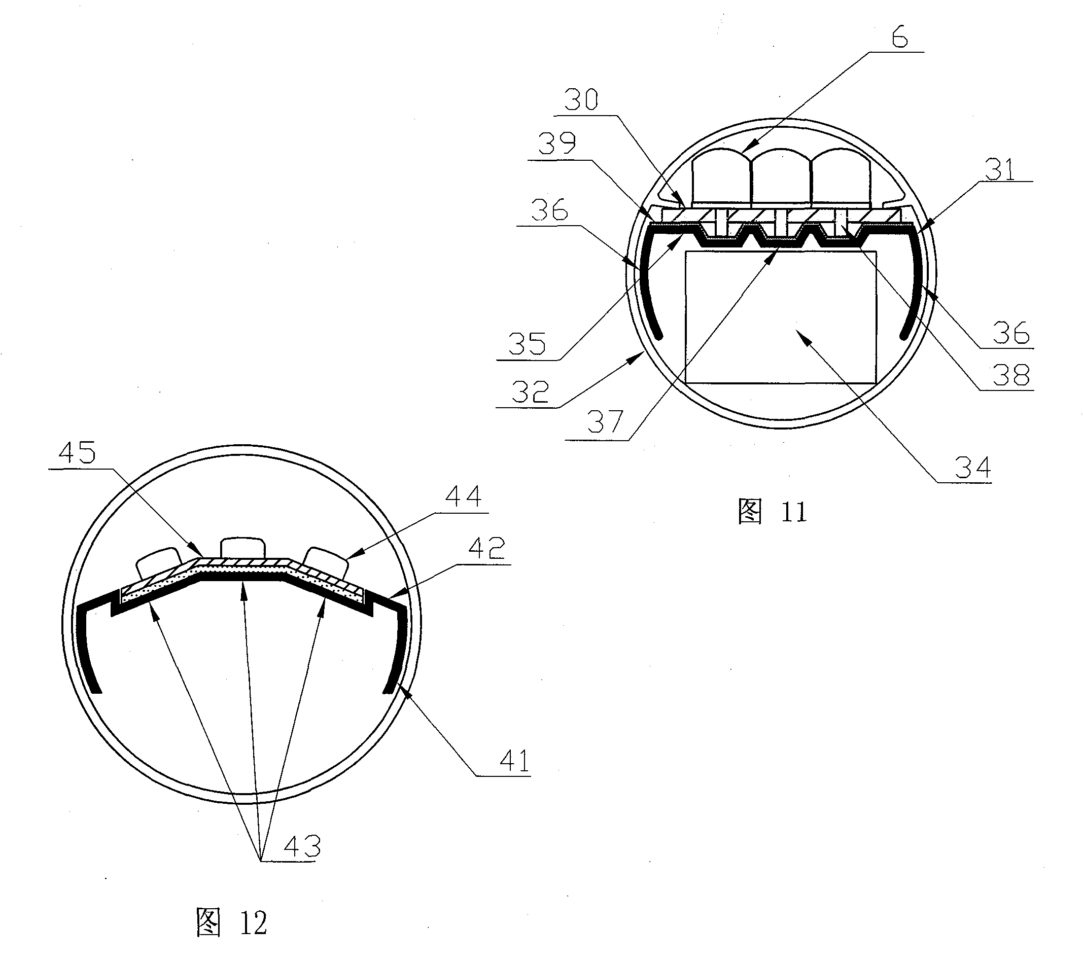
[0045] Such as Figure 10 , Figure 11As shown, it is composed of an LED lamp board 30, a lamp bead heat conducting sleeve 31, a lamp tube cover 32, a plug 33, and an LED constant current device 34. Bat-shaped, lamp bead heat conducting plate 35 is provided with more than one groove 37, the lamp bead pin 38 of LED lamp board 30 is placed in the groove 37, and put into the inner cavity of lamp tube outer cover 32 together, LED constant current The device 34 is placed in the hollow position where the lamp bead heat conduction sleeve 31 and the lamp tube cover 32 are combined. The outer diameter of the arc edge 36 on both sides of the bat-shaped lamp bead heat conduction sleeve 31 is slightly smaller than the inner diameter of the lamp tube cover 32, which is consistent with the lamp tube cover 32 inner walls are in contact with each other. The LED lamp board 30 is fixed on the lamp bead heat conduction sleeve 31 through heat conduction silica gel 39. In the middle of the lamp ...


PUM


Abstract

The invention relates to a heat-dissipation structure of a light-emitting diode (LED) daylight lamp. A metal heat-dissipation inner sleeve is arranged inside a glass tube outer cover or a full-plastic tube outer cover, an LED lamp panel is fixedly connected with a lamp bead heat conductive plate and is placed on bulged strips of the metal heat-dissipation inner sleeve, and two sides of the lamp bead heat conductive plate are attached to two inner sides of the metal heat-dissipation inner sleeve. The outer wall of the metal heat-dissipation inner sleeve is attached to the inner wall of the tube outer cover, and therefore the heat-dissipation area of the lamp bead heat conductive plate is increased, the requirement for the temperature for the long service lives of LED beads is basically met, and an LED galvanostat is convenient to assemble. The heat-dissipation structure of the LED daylight lamp enables products to meet the international electrotechnical commission 60598 (IEC) standard requirement, avoids the phenomenon of electric shock, guarantees safe use of the LED daylight lamp, and enables the service life of the LED daylight lamp to be effectively guaranteed at the same time, thereby effectively promoting the development of the LED daylight lamp.

Description

technical field [0001] The invention relates to the field of lighting, in particular to a heat dissipation structure of an LED fluorescent lamp. Background technique [0002] In order to solve the heat dissipation problem of the lamp beads, the existing LED fluorescent lamps mostly use aluminum substrates as the lamp board material plus a half-plastic half-aluminum lamp tube cover or a half-plastic half-fan-shaped radiator lamp tube cover, which plays a greater role in the LED lamp beads. Good heat dissipation, but the aluminum substrate has a large area, high cost, and exposed metal. For LED fluorescent lamps that use voltages above 36v, electric shocks are likely to occur, and safety is difficult to guarantee. Whether it is self-ballasted LED fluorescent lamps or external For LED fluorescent lamps with constant current devices, the creepage distance and electrical clearance required by the IEC60598 standard cannot be achieved for LED fluorescent lamps with a maximum diamet...

Claims


Application Information

Patent Timeline
IPC IPC(8): F21S2/00F21V29/00F21V19/00F21Y101/02F21K9/27F21V29/50F21Y115/10
Inventor 黄嘉宾
Owner 黄嘉宾
Why Eureka
Try Eureka