Identification method for space target rotation state based on binocular vision

A space target and rotation state technology, applied in the aerospace field, can solve problems such as the inability to guarantee the center point, the inability to identify the rotation axis and the rotation angular velocity, etc.

Active Publication Date: 2013-03-20
NORTHWESTERN POLYTECHNICAL UNIV
View PDF1 Cites 12 Cited by
  • Summary
  • Abstract
  • Description
  • Claims
  • Application Information

AI Technical Summary

Problems solved by technology

[0004] In recent years, with the development of computer vision, many target state recognition methods based on binocular vision have been proposed. Rotation describes the translation and rotation of the target in space. Since the selected center point cannot be guaranteed to be located on the rotation axis of the target, these methods do not have the ability to identify the rotation axis and rotational angular velocity of a purely rotating target.

Method used


Image

  • Identification method for space target rotation state based on binocular vision
  • Identification method for space target rotation state based on binocular vision
  • Identification method for space target rotation state based on binocular vision

Examples


specific Embodiment

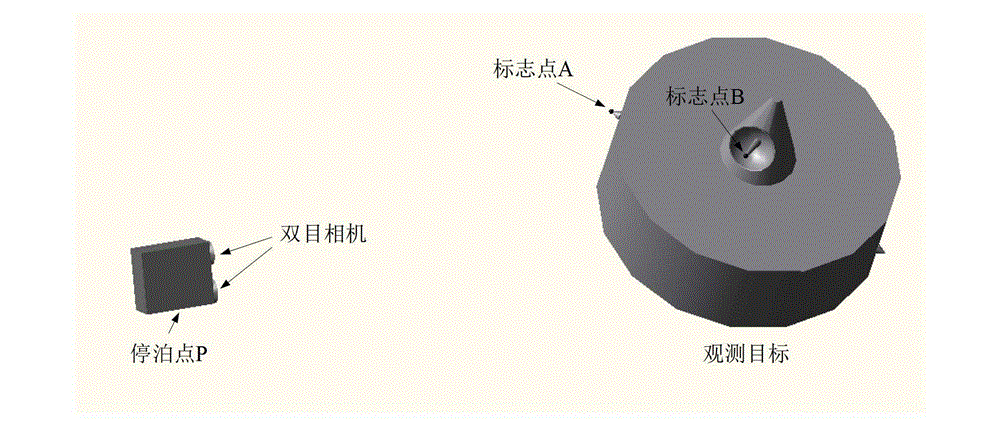
[0083] (1) Approaching the observation operation target:

[0084] Control the body equipped with a binocular camera to approach the target so that it parks at point P near the target, such as figure 1 As shown, select two marker points A and B on the target, observe the movement of the two points through the binocular camera, take ΔT=1s, the given position vector is as follows (unit: cm):

[0085] r A0 =(300,400,155.27864) T ;r B0 =(500,200,244.72136) T

[0086] r A1 =(442.68513,310.12752,102.46599) T ;

[0087] r B1 =(423.83306,162.06127,358.82704) T ;

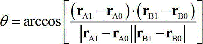
[0088] Compute the angular measure θ:

[0089]

[0090] Then satisfy |θ|>5° and |180-θ|>5°, so turn to step 2.

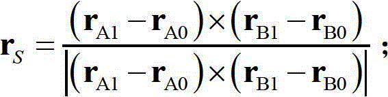
[0091] (2) Determine the direction vector of the rotation axis in the camera coordinate system:

[0092] Compute the vectors separately:

[0093] r flag =(r B0 -r A0 )×(r B1 -r A1 )=[-38028.76,-52958.39,-33383.66] T

[0094] r S = ...


PUM


Abstract

The invention relates to an identification method for a space target rotation state based on a binocular vision. The method comprises the steps that a binocular camera is arranged at an optional position P nearby a target; two optional mark points namely A and B on the target serve as characteristic points; a direction vector of a rotation axis is calculated; projections of the mark point A and the mark point B on a rotation plane are calculated; an rotation angle of the operating target is calculated; an angular rotation speed is calculated; and identification results of an angular rotation speed vector of the target and a rotation axis equation of the target are obtained. The method has the benefits that the method has the characteristics of less calculated amount, high identification speed, high identification precision, and easiness in realization; the deficiency that the existing method cannot identify the target rotation axis is overcome; and the method can be used for identifying rotation states of space targets, such as a self-rotation satellite and an uncontrolled rotation satellite, lays a foundation for close-range space operation on the space rotation targets, and has great utilization potentiality.

Description

technical field [0001] The invention belongs to aerospace technology, and in particular relates to a binocular vision-based method for recognizing the rotation state of a space target. Background technique [0002] In recent years, with the development of aerospace technology, space missions have become increasingly diverse and complex, and the demand for on-orbit service operations such as faulty satellite maintenance, enemy target monitoring and capture, and orbital garbage cleaning has become increasingly urgent. NASA, ESA and other large-scale Aerospace research institutions have also proposed their own research and experiment plans for on-orbit services, among which the more famous ones are NASA's XSS plan, ESA's ROTEX plan and ROGER plan, NASDA's ETS plan and so on. In order to realize the task requirements of the on-orbit service, the service body must be required to perform close-range high-precision operations on the service object. In addition, any slight collision...

Claims


Application Information

Patent Timeline
Patent Type & Authority Applications(China)
IPC IPC(8): G01P3/38G01P13/00G01P13/04
Inventor 黄攀峰胡仄虹刘正雄孟中杰
Owner NORTHWESTERN POLYTECHNICAL UNIV
Why Eureka
Try Eureka