Eureka AIR delivers breakthrough ideas for toughest innovation challenges, trusted by R&D personnel around the world.

Remote monitoring system for radar running status

A technology of remote monitoring and operating status, applied in the direction of electrical program control, comprehensive factory control, comprehensive factory control, etc., can solve the problems of reduced support efficiency, maintenance support difficulties, uneven technical levels of radar station maintenance support technicians, etc. To achieve the effect of life-cycle management

Inactive Publication Date: 2013-03-20
广为通讯技术(福建)有限公司
View PDF4 Cites 7 Cited by
  • Summary
  • Abstract
  • Description
  • Claims
  • Application Information

AI Technical Summary

Problems solved by technology

[0002] At present, there are mainly the following problems in the maintenance and guarantee of border and coastal defense radars and marine fishery radars: First, radar stations (duty points) are mostly located on the coastal line (or at sea), with scattered locations, inconvenient transportation, harsh environment and climate, and high radar failure rate , maintenance support is difficult; second, the technical level of the maintenance support technicians at the radar station (duty point) is uneven, and their ability to troubleshoot their own faults is weak; cumbersome, long round-trip cycle
When the radar station (duty point) is unable to troubleshoot, it can only rely on the superior to send personnel to the scene for emergency repairs, which consumes a lot of manpower, material and financial resources, delays a lot of time, reduces the support efficiency, and affects the smooth progress of the duty

Method used


Image

  • Remote monitoring system for radar running status
  • Remote monitoring system for radar running status
  • Remote monitoring system for radar running status

Examples


Embodiment Construction

[0021] The present invention will be further described below with reference to the accompanying drawings and embodiments.

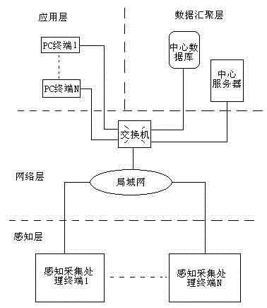
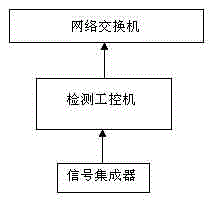
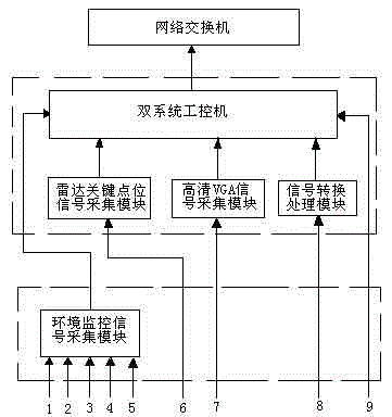
[0022] like figure 1 As shown in the figure, this embodiment provides a remote monitoring system for radar operation status, which is characterized in that: it consists of a perception layer, a data convergence layer and an application layer that communicate with each other via a network layer; the perception layer uses sensors to cooperate with acquisition and processing circuits to The radar state variables of the base station and the surrounding environment variables of the radar are converted into digital virtual quantities; the network layer mainly realizes the network topology of the system, the method of data transmission and network security measures; the data convergence layer is used to synchronize the data distributed and stored by each base station , and aggregate it into the data server in the center of the system; the application layer provi...


PUM


Abstract

The invention relates to the technical field of the radar monitoring, in particular to a remote monitoring system for radar running status. The system is formed by communicating a sensing layer, a data aggregation layer and an application layer through a network layer. By applying a sensor and cooperating an acquisition and processing circuit, the sensing layer converts the radar state variables of each base station and the radar surrounding variables into a digital virtual volume. The network layer mainly achieves the network topology of system, the mode of data transmission and the network security measure. The data aggregation layer is used for synchronizing the distributed memory data of each base station and aggregating the data to the center data server of the system. According to the needs of different users, the application layer provides the function of data access, data processing and visualization to the center and each radar station. According to the remote monitoring system for radar running status, the radar local intelligent maintenance and the remote long-distance expert online consultation is achieved, and therefore the preventative maintenance is reached and the life-cycle management and monitoring of the radar is achieved.

Description

technical field [0001] The invention relates to the technical field of radar monitoring, in particular to a remote monitoring system for radar operation status. Background technique [0002] At present, the maintenance and support of border and coastal defense radars and marine fishery radars mainly have the following problems: First, radar stations (duty points) are mostly located in the coastal line (or sea), with scattered locations, inconvenient transportation, harsh environment and climate, and high radar failure rate. , maintenance support is difficult; second, the technical level of maintenance support technicians at the radar station (duty point) is uneven, and their ability to troubleshoot is weak; third, the radar station (duty point) has limited detection and maintenance equipment, and it is difficult to raise spare parts. Cumbersome and long round-trip cycle. When the radar station (duty point) is unable to troubleshoot, it can only rely on the superior to send ...

Claims


Application Information

Patent Timeline
IPC IPC(8): G05B19/418
CPCY02P90/02
Inventor 李晓兵范飞跃汪璟玢姚仰光林为庆林敏
Owner 广为通讯技术(福建)有限公司
Why Eureka
Eureka Blog
Learn More