Method for reducing antenna mutual interference in wireless device and wireless device

A technology for wireless devices and antennas, which is applied in the field of reducing mutual interference between antennas and can solve problems such as antenna co-channel interference.

Inactive Publication Date: 2013-03-20
ZTE CORP
View PDF5 Cites 12 Cited by
  • Summary
  • Abstract
  • Description
  • Claims
  • Application Information

AI Technical Summary

Problems solved by technology

[0004] The technical problem to be solved by the present invention is to provide a method and wireless device for reducing mutual interference between antennas in wireless devices, which effectively improves the isolation between antennas

Method used


Image

  • Method for reducing antenna mutual interference in wireless device and wireless device
  • Method for reducing antenna mutual interference in wireless device and wireless device

Examples


Embodiment Construction

[0024] This implementation mode provides a method for reducing antenna mutual interference in a wireless device, and adopts the following technical solution:

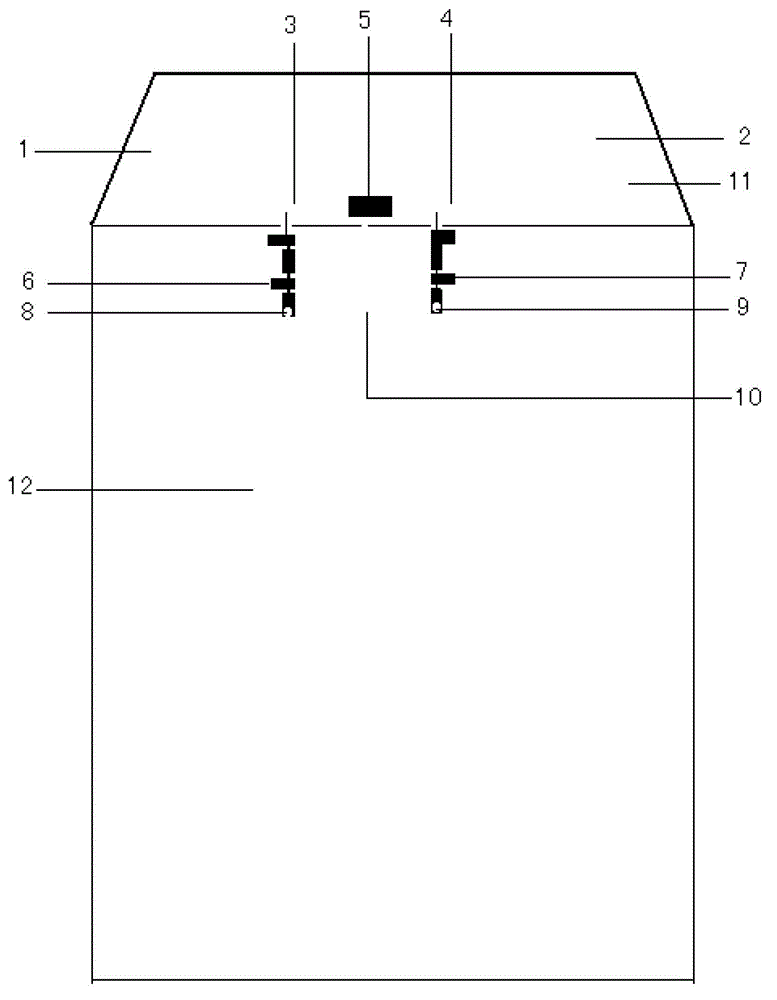
[0025] A section of microstrip line is respectively reserved at the front section of the wiring of the first antenna and the second antenna, and a capacitor is connected in series between the ends of the two sections of microstrip line.

[0026] In this way, the microstrip line, the series capacitor, and the antenna matching circuit together form a decoupling network to reduce the mutual coupling between the two antennas.

[0027] In addition, preferably, a "ground slot" method can also be used in the middle of the antenna to reduce the mutual interference of the floor current.

[0028] In addition, preferably, the position of the antenna can be arranged in any direction on the PCB board of the terminal, and can be adjusted according to layout requirements.

[0029] In addition, preferably, in this embodiment, there ma...


PUM


Abstract

The invention discloses a method for reducing antenna mutual interference in a wireless device and the wireless device. The wireless device comprises a first antenna and a second antenna, wherein a decoupling circuit is arranged between the first antenna and the second antenna, and the decoupling circuit is matched with the first antenna and the second antenna to form a decoupling network. According to the method and the wireless device, isolation between antennas is effectively improved, the objective problem of co-channel interference between antennas in long term evolution (LTE) products at present is solved, and the miniaturized layout requirement for terminal products such as data cards and mobile phones is satisfied simultaneously.

Description

technical field [0001] The present invention relates to the technical field of wireless communication, in particular to a method for reducing antenna mutual interference in a wireless device and the wireless device. Background technique [0002] The emergence of LTE (Long Term Evolution, long-term evolution) technology has promoted the development of wireless broadband access technology and industry. It is required to provide a higher transmission rate. A wireless device often has two or more antennas at the same time. These antennas usually work in the same frequency band and are limited by product size requirements. There is inevitably co-channel interference between antennas. This is a problem for current LTE products. . [0003] In order to solve this technical problem, the traditional solution is to place the antennas working in the same frequency band at a physical location far enough away, and the isolation of the antennas is large enough, so that the layout can ach...

Claims


Application Information

Patent Timeline
IPC IPC(8): H01Q1/52H01Q21/00
CPCH01Q21/28H01Q1/521H01Q1/24
Inventor 马金萍孙飞飞刘洋
Owner ZTE CORP
Why Eureka
Try Eureka