Positioning device for blind nut hand tool

A positioning device and hand tool technology, applied in the field of positioning devices, can solve the problems of long assembly time, high processing cost, falling off of positioning steel ball 71, etc., achieve the effect of safe operation and reduce processing cost

Active Publication Date: 2013-03-27
KARAT INDAL CORP
View PDF6 Cites 3 Cited by
  • Summary
  • Abstract
  • Description
  • Claims
  • Application Information

AI Technical Summary

Problems solved by technology

[0007] 1. The installation of the positioning device requires complicated procedures such as drilling the positioning hole 70, inserting the positioning steel ball 71, inserting the small spring 72, and screwing the assembly bolt 73. Not only the processing cost is high, but also considerable assembly time is required
[0008] 2. When the rotary head 552 drills the positioning hole 70, due to the difficulty in processing, it is easy to produce a penetration phenomenon, causing the positioning steel ball 71 to fall off due to the pull rod 60 being pulled away from the rotary head 552, and the positioning effect is lost.
[0010] 4. Please refer to Figure 7 As shown, the positioning steel ball 71 contacts the surface of the positioning groove 63 of the pull rod 60 at a single point, and the contact area between the two is too small. During actual operation, the pull rod 60 may still loosen, resulting in a poor positioning effect.
[0011] Therefore, the positioning device of the cap pulling hand tool of the prior art still has the above-mentioned shortcomings to be improved
[0012] In view of the disadvantages of the positioning device of the cap pulling hand tool in the prior art, such as high processing cost, long assembly time, easy falling off of the positioning steel ball due to processing failure, and poor positioning effect, the present invention improves on these shortcomings

Method used


Image

  • Positioning device for blind nut hand tool
  • Positioning device for blind nut hand tool
  • Positioning device for blind nut hand tool

Examples


Embodiment Construction

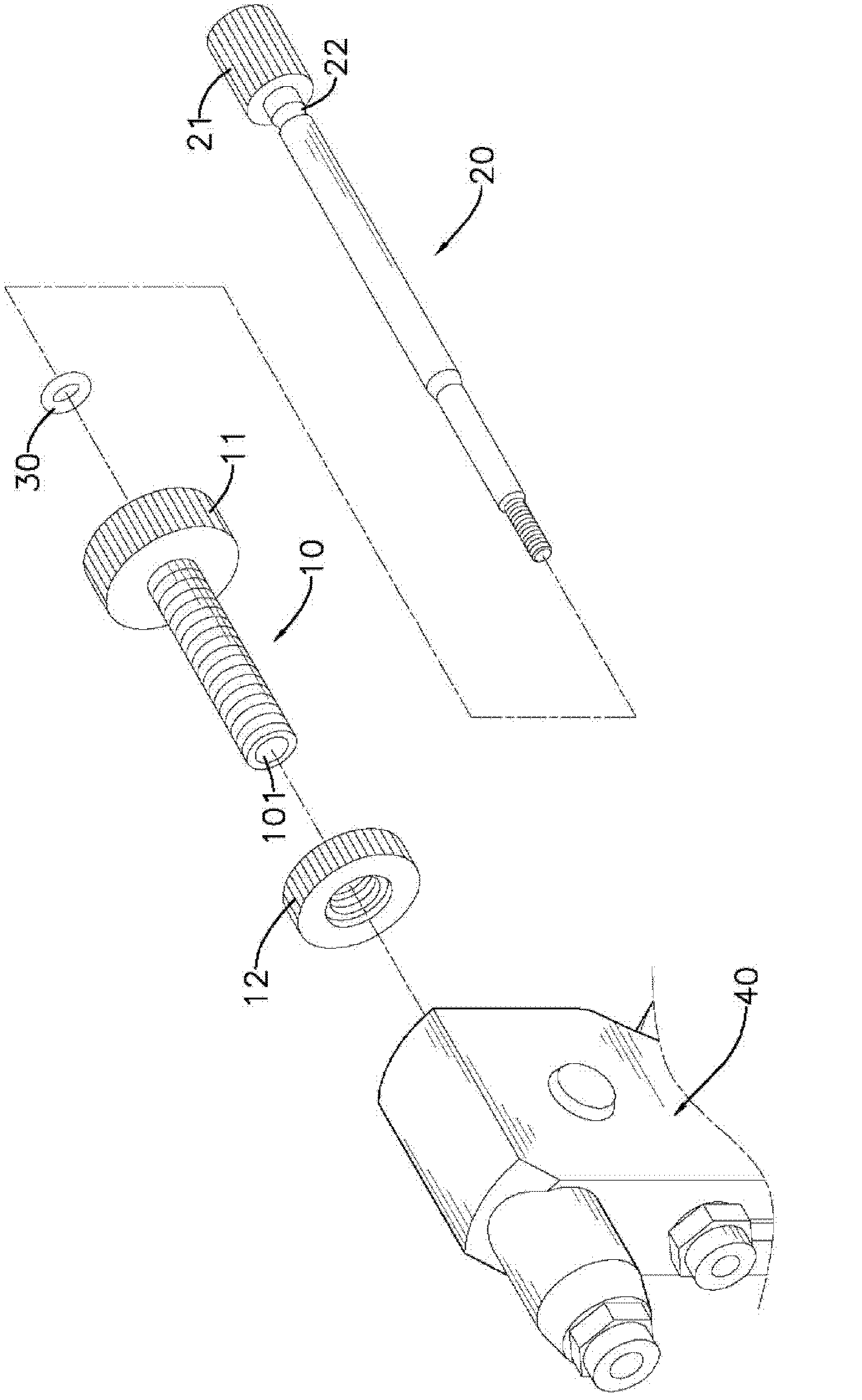
[0046] The present invention is a positioning device for a cap pulling hand tool, please refer to figure 1 As shown, it includes a rotating sleeve 10, a pull rod 20 and a positioning ring 30;

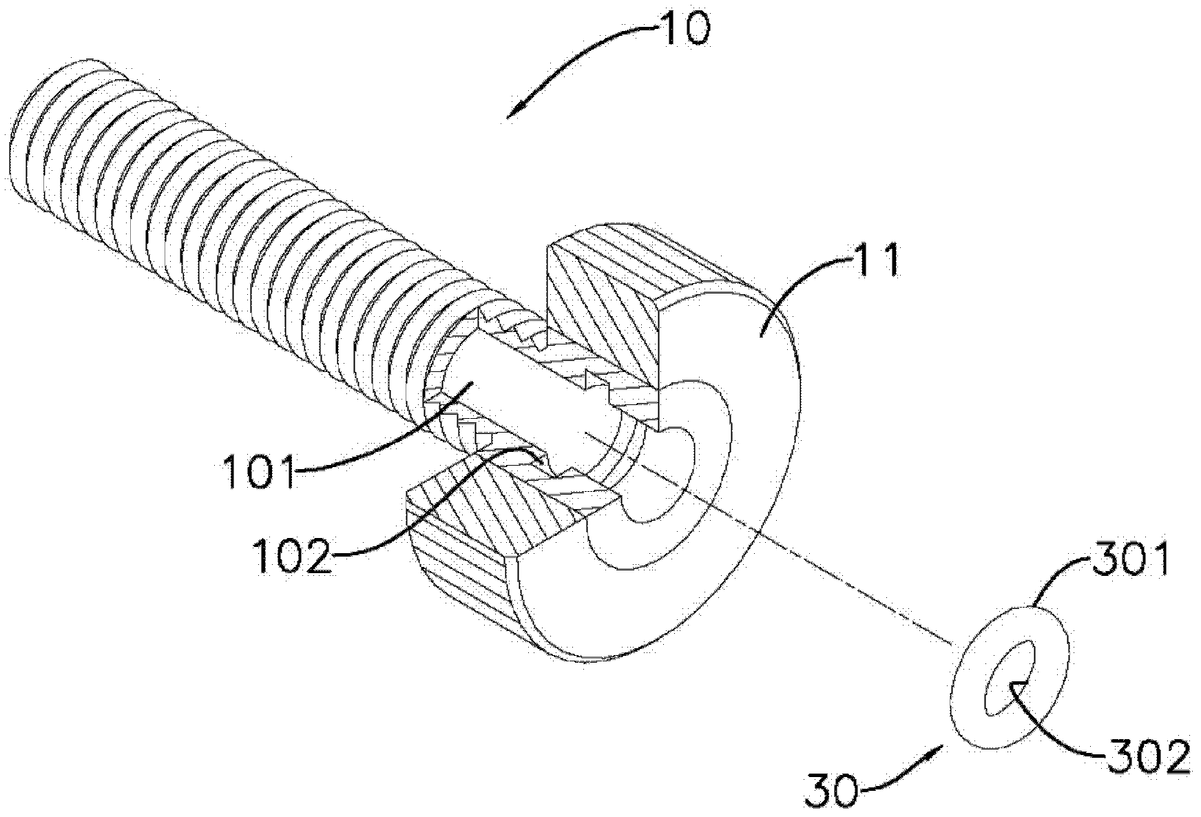
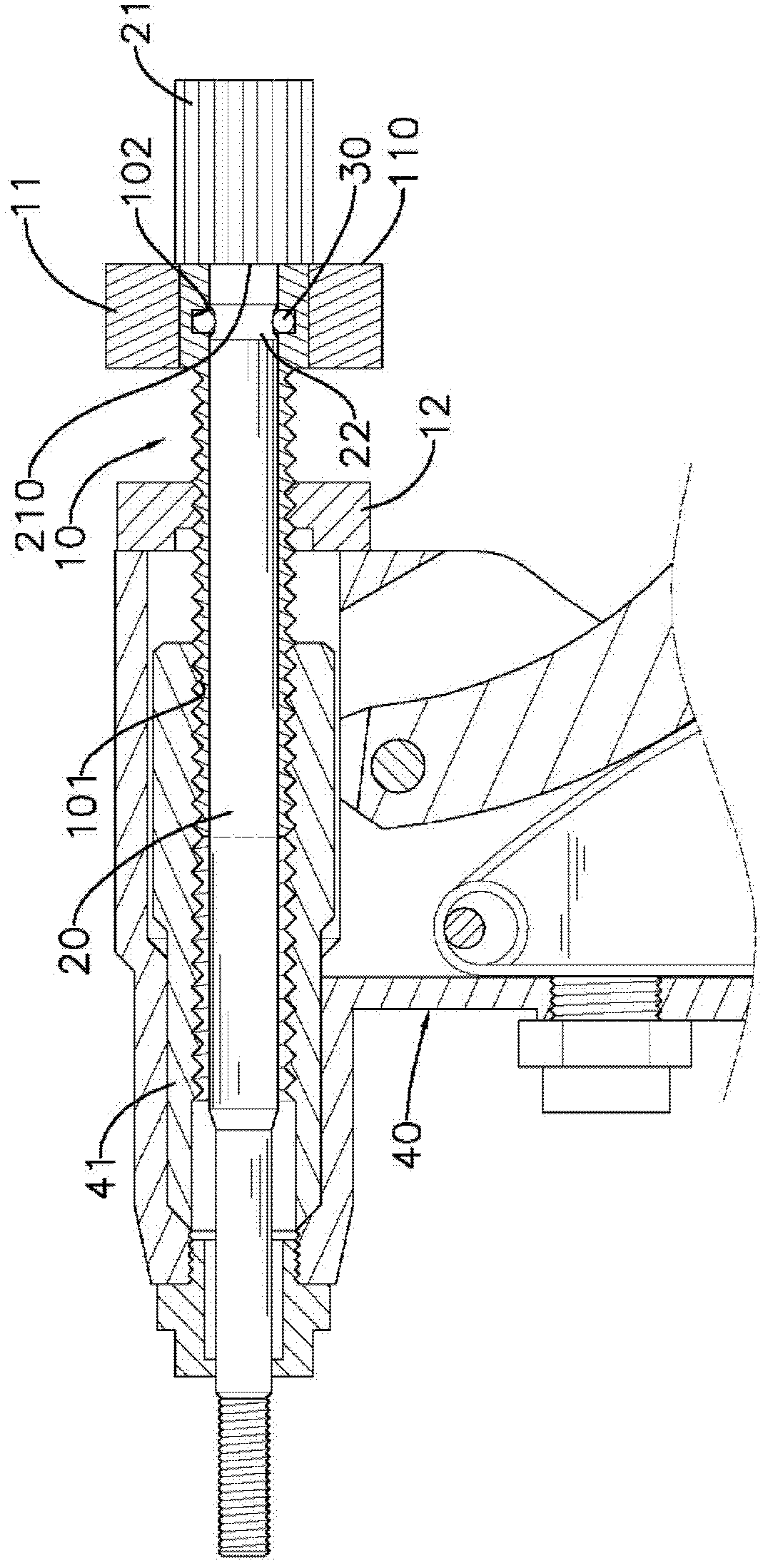
[0047] Please refer to figure 2 and image 3 As shown, the rotating sleeve 10 is a hollow tube with openings at both ends, and a rotating head 11 is sleeved on one end of the rotating sleeve 10. The outer pipe wall of the rotating sleeve 10 is provided with external threads. The inner tube wall of the sleeve 10 forms a through hole 101, and the inner hole surface at the end of the rotating head 11 is radially recessed with an annular mounting groove 102. In a preferred embodiment of the present invention, the mounting groove 102 is located at the The center of the axial position of the rotary head 11;

[0048] The pull rod 20 is a round rod. The outer diameter of the rod body is smaller than the aperture of the through hole 101. One end of the rod body is connected with a pull rod ...


PUM


Abstract

The invention relates to a positioning device for a blind nut hand tool, which comprises a rotating sleeve, a pull rod and a positioning ring. An installation groove is formed inside a through hole at the position of a rotating head of the rotating sleeve; the positioning ring is arranged in the installation groove by an outer lateral ring surface; the pull rod is provided with a positioning groove corresponding to the positioning ring, and thus, when the pull rod moves to be inserted into the through hole, an inner lateral ring surface of the positioning ring is elastically sleeved on the positioning groove and a pull rod head can be surely positioned at a fixed position without shaking, so that the blind nut hand tool can stably rivet a blind nut on a workpiece. According to the device, by the technical means, a positioning device in the prior art is simplified, assembly labor hours and cost can be reduced and a better positioning effect is provided.

Description

technical field [0001] The invention relates to a positioning device, in particular to a positioning device for a cap pulling hand tool. Background technique [0002] Pull cap hand tool, which can be used to set the pull cap (English RIVET NUT or THREADED INSERT) with multi-turn screw internal threads on the workpiece, especially on thin workpieces, so that multi-turn screw internal threads can be established on the workpiece. For example: Drill a hole on a plate-shaped metal workpiece before installing a pull cap. The lower half of the pull cap axis is provided with a multi-turn screw hole internal thread, and the external thread at one end of the pull rod of the hand tool is combined with the internal thread of the pull cap. And apply an external force to force the thin wall on the upper half of the pull cap to produce compression deformation, so as to rivet and fix the pull cap on the plate metal to establish a multi-turn internal thread of the screw hole, so that the sec...

Claims


Application Information

Patent Timeline
Patent Type & Authority Applications(China)
IPC IPC(8): B21J15/38
Inventor 柯永昌
Owner KARAT INDAL CORP
Why Eureka
Try Eureka