Hydraulic chuck turning clamp of numerically controlled lathe

A technology of hydraulic chuck and CNC lathe, which is applied in the direction of clamping, manufacturing tools, supports, etc., which can solve the problems of unguaranteed turning quality, easy deformation of the clamping surface of soft jaws, and affecting the processing quality of workpieces, etc. Low cost, small degree of deformation, and the effect of ensuring turning quality

Inactive Publication Date: 2013-03-27
顾林男
View PDF0 Cites 8 Cited by
  • Summary
  • Abstract
  • Description
  • Claims
  • Application Information

AI Technical Summary

Problems solved by technology

The existing turning methods are as attached figure 2 As shown, a circular support plate 3 is clamped inside the soft jaw of the hydraulic chuck to support the soft jaw, and then the clamping surface of the soft jaw is turned, so that the diameter of the clamping surface of the soft jaw is the same as that of the clamped part of the workpiece As the position for clamping the workpiece, the soft jaws with different sizes need to use support plates with different diameters. Therefore, before the turning soft jaws are clamped, it is necessary to prepare a variety of support plates with different specifications in advance, which increases the turning cost; The support plate is clamped inside the soft jaws, and the clamping surface of the soft jaws cannot be completely turned, and during the clamping process, the clamping surface of the soft jaws is easily deformed, so the turning quality cannot be guaranteed, which affects the processing of the workpiece quality

Method used


Image

  • Hydraulic chuck turning clamp of numerically controlled lathe
  • Hydraulic chuck turning clamp of numerically controlled lathe
  • Hydraulic chuck turning clamp of numerically controlled lathe

Examples


Embodiment Construction

[0016] The present invention will be described below with reference to the drawings.

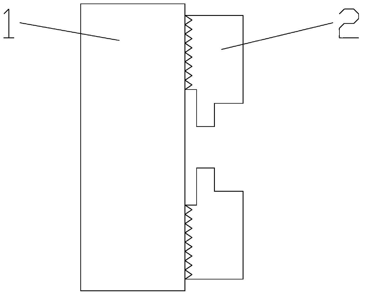
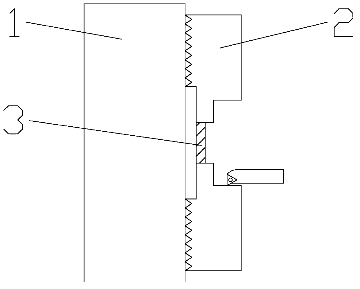
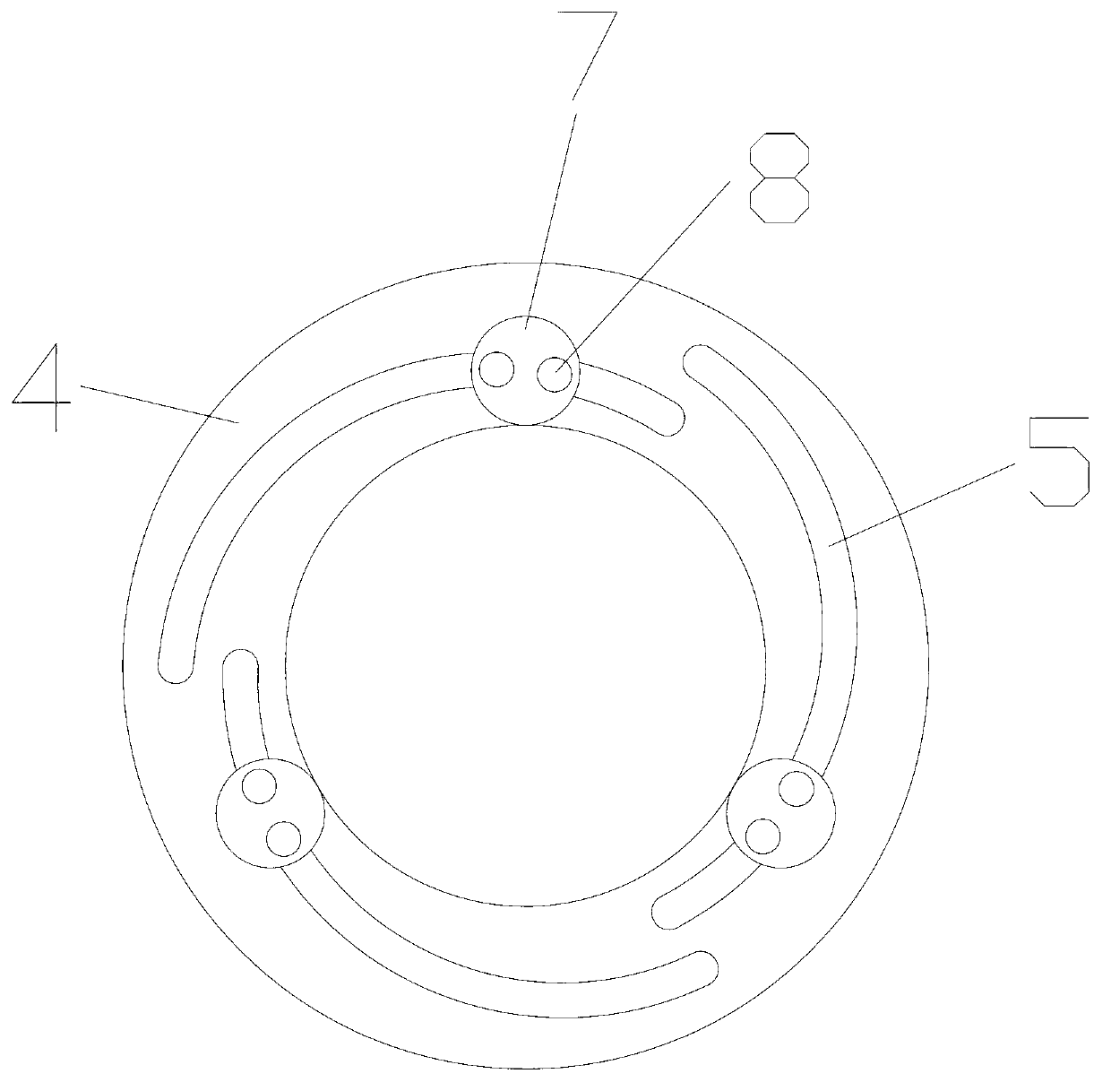
[0017] As attached image 3 , 4 The hydraulic chuck turning fixture of a numerical control lathe according to the present invention shown in the present invention includes a circular ring clamp body 4; the circular ring clamp body 4 is provided with three identical non-concentric arc grooves 5; Each arc groove 5 is provided with a fixing pin 6 that can slide in the arc groove; the outer end of the fixing pin 6 is fixed with a stopper 7 by a fastener; the fastener 8 is a screw.

[0018] As attached Figure 5 The hydraulic chuck turning fixture of a numerical control lathe according to the present invention is shown. When in use, three fixing pins 6 are respectively inserted into the screw counterbores 9 of the soft jaw 2. When the soft jaw 2 is closed, the three fixed The pin 6 can be automatically adjusted to the best position to clamp the soft jaw 2 and then turn the clamping surface of the sof...


PUM


Abstract

The invention discloses a hydraulic chuck turning clamp of a numerically controlled lathe. The hydraulic chuck turning clamp comprises a circular clamp body, wherein three same arc chutes which are not concentric are arranged on the circular clamp body; a fixing pin capable of sliding in each arc chute is arranged inside each arc chute, and a baffle block is fixed at the outer end of the fixing pin through a fastener. According to the hydraulic chuck turning clamp of the numerically controlled lathe disclosed by the invention, the fixing pin is long in sliding travel route inside each arc chute, and suitable for soft claws with different clamping sizes, saves various support plates with different dimensions, and reduces the turning cost; the deformation degree of the clamping surface of each soft claw is small; the hinder of each support plate disappears in the turning process; the clamping surface of each soft claw can be completely turned; and the turning quality is guaranteed, so as to increase the processing quality of a work-piece.

Description

Technical field [0001] The invention relates to a clamp, in particular to a clamp for turning a soft jaw clamping surface of a hydraulic chuck of a numerical control lathe. Background technique [0002] CNC lathes generally use hydraulic chucks to clamp the workpiece. Hydraulic chucks are usually equipped with unhardened jaws, so-called soft jaws. The structure of the hydraulic chuck is as attached figure 1 As shown, it includes a chuck body 1 and a soft jaw 2. When the hydraulic chuck is working, the soft jaw makes a closing or opening movement to clamp or loosen the workpiece. When processing large batches of shaft or disc parts, in order to prevent damage to the processed surface of the workpiece, and to ensure the coaxiality requirements of the workpiece surface and the workpiece surface, the clamping surface of the soft jaw of the hydraulic chuck Turn it. The existing turning methods are as attached figure 2 As shown, a circular support plate 3 is clamped inside the soft...

Claims


Application Information

Patent Timeline
Patent Type & Authority Applications(China)
IPC IPC(8): B23Q3/00
Inventor 顾林男
Owner 顾林男
Why Eureka
Try Eureka