Tool Grinding Fixtures

A tool grinding and fixture technology, applied in the field of tool grinding fixtures, can solve the problems of low machining accuracy and low machining efficiency of cylindrical solid tools, and achieve the effect of improving accuracy and speed

Active Publication Date: 2015-08-19
FUNIK ULTRAHARD MATERIAL
View PDF12 Cites 0 Cited by
  • Summary
  • Abstract
  • Description
  • Claims
  • Application Information

AI Technical Summary

Problems solved by technology

[0003] The Chinese invention patent with the notification number CN201645276U discloses a sheet tool grinding jig for grinding machines. The jig includes a jig body and a tapered screw. ) on the tail handle rod and the front end are provided with an expansion body with a circular cross-section for clamping the tool to be ground. The tail handle rod is a Morse taper handle, and the expansion body is a four-petal fixed diameter The retractable claws are provided with internal threads on the inner surface of the expansion body for screwing with the conical screw. , and then by tightening the conical screw on the expansion body, so that the four-lobed claws are all spread out to tighten the sheet tool to be ground, and position the sheet tool to be ground, so that the scope of application of the fixture Effective, that is, it is mainly suitable for the grinding of ring tools, but for ordinary solid cylindrical tools, the fixture can be clamped and positioned, so that cylindrical solid tools still need to be ground by hand, so that the columnar solid The cutting tool still has the problems of low processing efficiency and low processing accuracy

Method used


Image

  • Tool Grinding Fixtures
  • Tool Grinding Fixtures
  • Tool Grinding Fixtures

Examples


Embodiment Construction

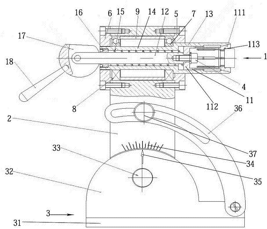
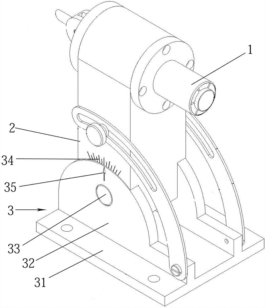
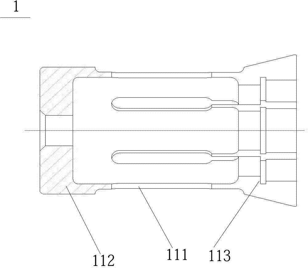
[0021] Embodiments of the tool grinding fixture of the present invention: as Figure 1 to Figure 4 As shown, the clamp includes a clamp body 1, a clamp seat 2 and a base 3 arranged sequentially from top to bottom, wherein the clamp body 1 includes an expansion body 11, a tail handle rod 12, a mounting sleeve 13, a positioning sleeve 14, and a return spring 15 , Plug 16, eccentric wheel 17 and handle 18. The expansion body 11 is composed of an annular guide plate 111 fixed on the front end of the tail handle rod 12 through the connecting screw 4, and four annular claws 112 that can be radially opened and closed at intervals on the outer edge of the guide plate 111. The rear end of the claw 112 is annularly distributed on the front end surface of the handle 18 rod. The front end is in an open state when it is exposed from the front end of the installation sleeve 13, and is inwardly folded when it is received in the installation sleeve 13. At the clamping end in the folded state...


PUM


Abstract

The invention discloses a cutter grinding fixture. The periphery of each elastic piece in a fixture body is provided with a mounting sleeve, the front ends of the elastic pieces are provided with clamping ends, and the clamping ends open outwards to be at an open state when the elastic pieces reveals from the from ends of the mounting sleeves and closes inwards to be at a closed state when the elastic pieces are withdrawn into the mounting sleeves. Hole walls or front end ports of the mounting sleeves are provided with close-up edges, and the close-up edges are matched with elastic claws along the anterior-posterior direction in stopping mode when the clamping ends are at the open state and stops the clamping ends on the peripheries of the elastic claws when the clamping ends are at the closed state. In use, opening and closing movements of the elastic claws can be achieved through matching between the close-up edges and the clamping ends, accordingly column-shaped solid cutters to be grinded can be tightly clamped, and further clamping speed of the column-shaped solid cutters is improved. Automatic centering can be achieved through wedge surface matching, and accuracy of column-shaped solid cutter clamping and cutter grinding processing can be improved.

Description

technical field [0001] The invention relates to the technical field of tool grinding fixtures. Background technique [0002] At present, the grinding of the blade of the tool is usually done manually. When the grinding wheel is grinding the tool head, the handle of the tool is held tightly by hand to achieve the grinding of the tool. This method not only increases the labor of the staff Intensity, and the amount of grinding in the grinding process needs to be determined by the experience of the staff, thereby reducing the accuracy of the grinding process and reducing the processing efficiency. [0003] The Chinese invention patent with the notification number CN201645276U discloses a sheet tool grinding jig for grinding machines. The jig includes a jig body and a tapered screw. ) on the tail handle rod and the front end are provided with an expansion body with a circular cross-section for clamping the tool to be ground. The tail handle rod is a Morse taper handle, and the e...

Claims


Application Information

Patent Timeline
Patent Type & Authority Patents(China)
IPC IPC(8): B24B3/00
Inventor 邢建军王喜宏
Owner FUNIK ULTRAHARD MATERIAL
Why Eureka
Try Eureka