Speed giving driver controller of electric locomotive

A driver controller, speed given technology, applied in locomotives and other directions, can solve the problems of reducing economic benefits, social benefits, distracting drivers, locomotive speed and safety can not be well balanced, etc., to improve economic and social benefits. Benefit, avoid misoperation by human factors, and improve the effect of line traffic capacity

Active Publication Date: 2013-03-27
CSR CHENGDU
View PDF6 Cites 6 Cited by
  • Summary
  • Abstract
  • Description
  • Claims
  • Application Information

AI Technical Summary

Problems solved by technology

[0003] 1. The potentiometer is easy to wear due to the sliding contacts, which will lead to changes in resistance and poor contact. In actual use, not only the failure rate is high, but also the command signal is unstable, and even the locomotive runs away, causing safety accidents.
[0004] 2. Due to the deviation of human judgment, the weakening of the magnetic field is often advanced or delayed
If the weakening of the magnetic field is advanced, the current of the traction motor will be large, the temperature will rise, and the insulation will drop; if the weakening of the magnetic field is delayed, the voltage between the commutator plates of the traction motor will be too high, which will increase the commutation spark
In short, both will seriously affect the normal work of the traction motor
[0005] 3. The speed of the locomotive and the weakening of the magnetic field cannot be controlled automatically
In order to ensure the punctual and safe operation of the locomotive, the driver must keep an eye on the road conditions and signal status ahead at any time, understand the actual speed of the locomotive, monitor the speed limit, and combine other driving status information to frequently operate the driver's controller. The workload is heavy and the driver's attention is distracted. , the speed and safety of the locomotive can not be well taken into account, and the running speed is often low enough to ensure the safety of driving, and the driving of the line is not well utilized, which reduces the economic and social benefits

Method used


Image

  • Speed giving driver controller of electric locomotive

Examples


Embodiment

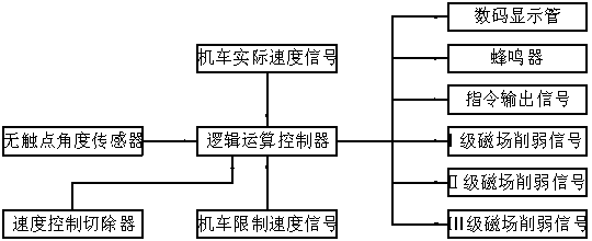
[0016] Example: such as figure 1 As shown, a speed given driver controller for an electric locomotive includes a non-contact angle sensor, a logic operation controller, a speed control cutter, a digital display tube and a buzzer, and the logic operation controller is respectively connected with a non-contact Angle sensor, speed control cutter, digital display tube, buzzer are connected, and the logic operation controller is also equipped with locomotive actual speed signal interface, speed limit signal interface, command signal output interface and I, II, III magnetic field weakening Signal output interface.

[0017] The non-contact angle sensor is used for the generation of the locomotive speed given value signal, and its rotation angle corresponds to the locomotive speed given value signal.

[0018] The speed control cutter is used to cut off the control function of the actual speed signal of the locomotive and the limited speed signal of the locomotive respectively.

[00...


PUM


Abstract

The invention discloses a speed giving driver controller of an electric locomotive. The speed giving driver controller comprises a non-contact angle sensor, a logic operation control unit, a speed control remover, a digital display tube and a buzzer, wherein the logic operation control unit is connected with the non-contact angle sensor, the speed control remover, the digital display tube and the buzzer respectively; and the logic operation control unit is further provided with an actual locomotive speed signal connector, a limited speed signal connector, an instruction signal output connector, and I-grade, II-grade and III-grade magnetic field weakening signal output connectors. The speed giving driver controller of the electric locomotive has the beneficial effects that the non-contact angle sensor is adopted and an instruction signal is stable; a fault caused by abrasion is avoided and maintenance-free operation can be realized; locomotive constant-speed giving is automatically controlled and the speed giving driver controller effectively guarantees that the locomotive can operate safely at the highest speed; magnetic weakening is automatically controlled; and after a speed control function is removed, all functions of a common driver controller can also be finished.

Description

technical field [0001] The invention relates to the technical field of locomotive control devices, in particular to a speed setting driver controller for an electric locomotive. Background technique [0002] At present, the speed control handles of all Shaoshan type electric locomotive driver controllers drive the potentiometer through the rotating shaft, and the potentiometer then outputs the corresponding speed control command signal to the electronic cabinet. In addition, the stepped control of magnetic field weakening relies entirely on the driver's controller's speed control handle and reversing handle for manual control, and the actual speed of the locomotive is not introduced for comparison. These control methods have at least the following deficiencies: [0003] 1. The potentiometer is easy to wear due to the sliding contact, which leads to the change of resistance value and poor contact. In actual use, not only the failure rate is high, but also the command signal ...

Claims


Application Information

Patent Timeline
Patent Type & Authority Applications(China)
IPC IPC(8): B61C17/00
Inventor 黎长富
Owner CSR CHENGDU
Why Eureka
Try Eureka