Computer laser embroidering machine

An embroidery machine and laser technology, which is applied in the field of textile and embroidery machines, can solve problems affecting the sales of laser embroidery machines, poor maintenance of optical fibers, and easy sintering damage of optical fibers, etc., and achieve stable and reliable light emitting points, low environmental requirements, and high safety. Effect

Inactive Publication Date: 2013-03-27
上工富怡智能制造(天津)有限公司
View PDF1 Cites 2 Cited by
  • Summary
  • Abstract
  • Description
  • Claims
  • Application Information

AI Technical Summary

Problems solved by technology

[0004] However, the above-mentioned technology adopts the optical fiber laser transmission method. The main problem of this method is that the optical fiber is easy to be sintered and damaged after working for a long time. At the same time, the maintenance of the optical fiber is relatively poor, and the customer's use cost is relatively high.
This deficiency has affected the sales of laser embroidery machines, especially for cutting denim, artificial leather and other relatively advanced fabrics, which require a lot of power, which requires a transmission device that can stably deliver high-power lasers

Method used


Image

  • Computer laser embroidering machine
  • Computer laser embroidering machine
  • Computer laser embroidering machine

Examples


Embodiment Construction

[0013] The structure of the present invention will be described in detail below in conjunction with the accompanying drawings.

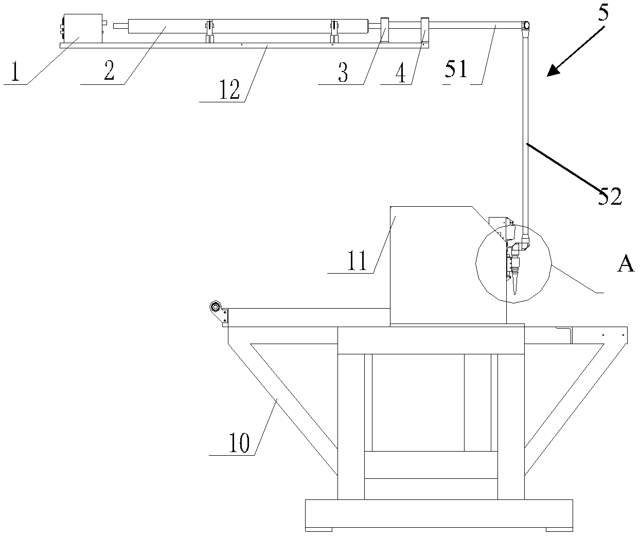
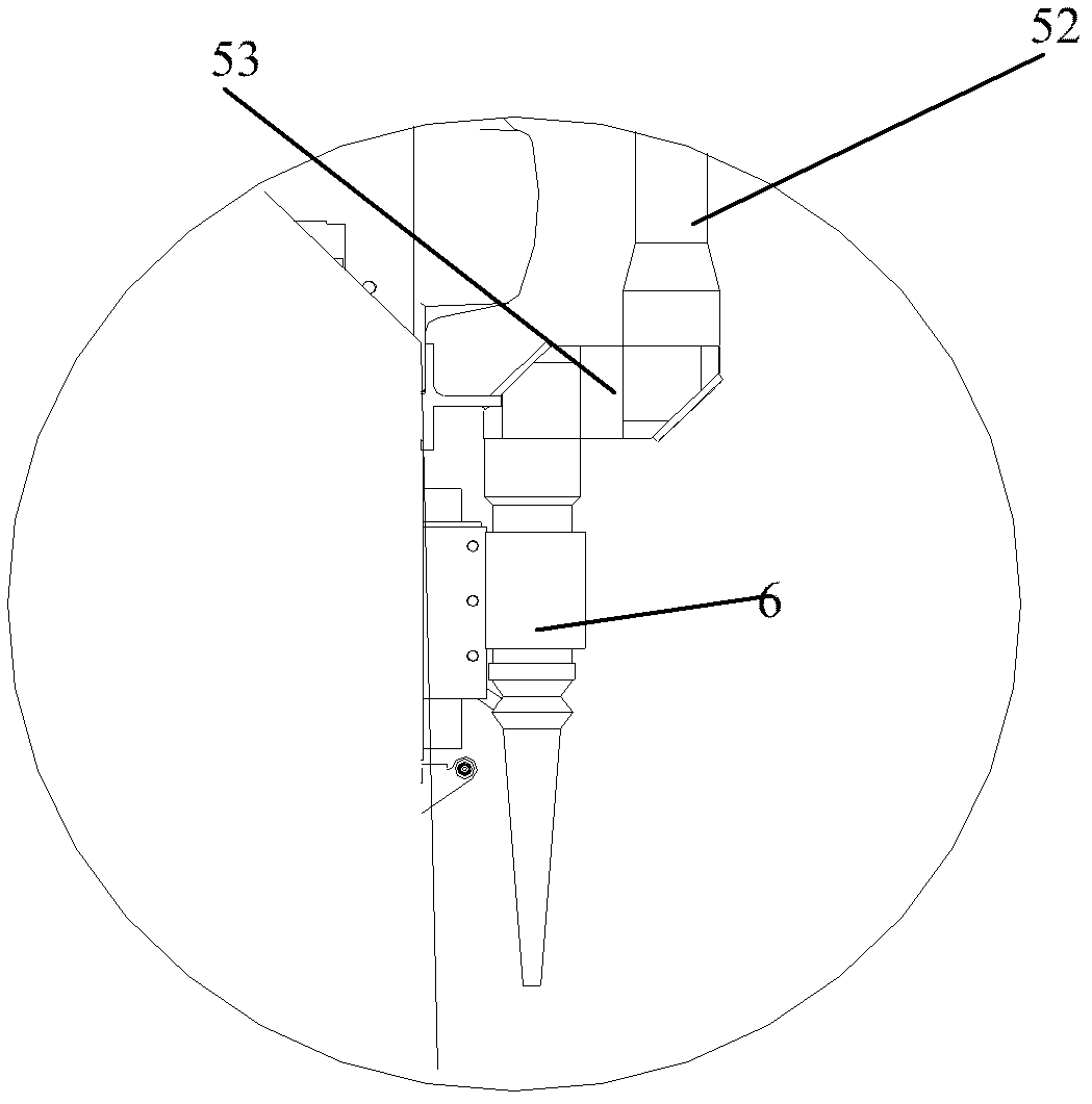
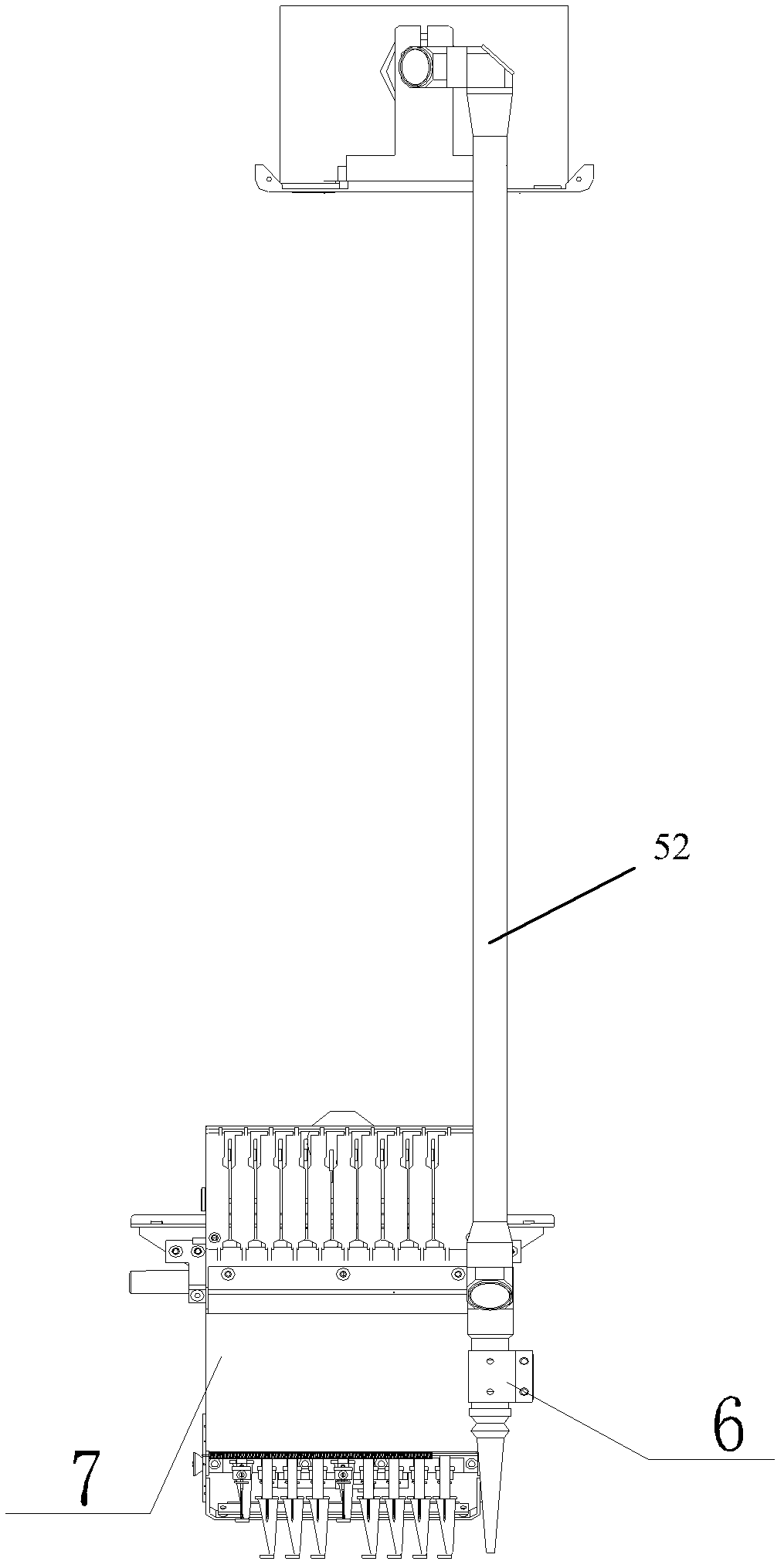
[0014] Such as Figure 1-3 Shown, computerized laser embroidery machine of the present invention comprises laser power supply 1, laser generator 2, frame 10, the crossbeam 11 that is fixed on the frame 10, the embroidery machine needle bar case 7 that is installed on the crossbeam 11 and is installed in embroidery The laser cutting head 6 on one side of the needle bar box 7 of the machine, the laser power supply and the laser generator 2 are fixedly arranged on the upper beam 12 fixedly connected with the frame, wherein the laser generator 10 is generally CO 2 A glass tube laser generator, the laser light emitted by the laser generator 10 is focused and then enters the multi-movable joint chamber reflective device (or laser tunnel for short) 5 and transmits to the laser cutting head 6.

[0015] Such as figure 1 , figure 2 As shown, the multi-mov...


PUM


Abstract

The present invention discloses a computer laser embroidering machine, which comprises a laser power supply, a laser generator, a frame, a girder fixed on the frame, an embroidering machine needle rod box installed on the girder and a laser cutting tool bit installed on one side of the embroidering machine needle rod box, wherein the laser power supply and the laser generator are fixedly arranged on an upper beam fixedly connected with the frame, and a multi-movement joint chamber light reflection device for laser transmission is arranged between the laser generator and the laser cutting tool bit. According to the present invention, the multi-movement joint chamber light reflection technology is adopted in the computer laser embroidering machine, such that the optical path has advantages of the reflector transmission mode, has good sealing, and is separated from air dust so as to ensure low loss of laser transmission and high safety; with arrangements of various joints, characteristics of the flexible optical path are provided, and characteristics of optical fibers are provided; and optical path adjustment is simple, reliability is high, a service life is long, high work light power can be carried during efficient cutting, light production points are stable and reliable, and requirements on the surrounding environment are low.

Description

technical field [0001] The invention belongs to the embroidery machine and textile industries, in particular to a laser computerized embroidery machine utilizing laser cutting. Background technique [0002] At present, the existing laser embroidery technology in the computer embroidery industry generally uses reflection technology to reflect the laser light generated in the laser generator to the laser cutter head for cutting or carving operations. The more commonly used laser generators on the market are CO 2 For the glass tube laser generator, in order to shorten the laser transmission line, the glass tubes are usually divided into the beam of the embroidery machine. [0003] Chinese patent 201020638926.0 discloses a computer laser embroidery machine, including a laser generator, a frame, a beam fixed on the frame, an embroidery machine needle bar box installed on the beam, and a laser cutter head installed beside the embroidery machine needle bar box The laser emitted by...

Claims


Application Information

Patent Timeline
Patent Type & Authority Applications(China)
IPC IPC(8): D05C7/00D05C13/00
Inventor 高接枝
Owner 上工富怡智能制造(天津)有限公司
Why Eureka
Try Eureka