Thin composite multiple-layer band gap microwave dark chamber wall body liner

A technology of microwave anechoic chamber and wall lining, applied in the field of microwave anechoic chamber, can solve the problems of high cost, reduce material volume and weight, etc., and achieve the effects of increasing resonance loss, reducing reflection amount, and increasing low-frequency resonance.

Active Publication Date: 2013-03-27
SOUTHEAST UNIV
View PDF6 Cites 2 Cited by
  • Summary
  • Abstract
  • Description
  • Claims
  • Application Information

AI Technical Summary

Problems solved by technology

Although these improvements have improved the performance of the lining material, they have not significantly reduced the volume and weight of the material, so they are only suitable for microwave anechoic chambers with large spaces.
This traditional microwave anechoic chamber has excellent performance and wide versatility, but the cost is very high

Method used


Image

  • Thin composite multiple-layer band gap microwave dark chamber wall body liner
  • Thin composite multiple-layer band gap microwave dark chamber wall body liner
  • Thin composite multiple-layer band gap microwave dark chamber wall body liner

Examples


Embodiment Construction

[0034] The present invention will be further described below in conjunction with the accompanying drawings and embodiments, and the purpose and effect of the present invention will become more obvious.

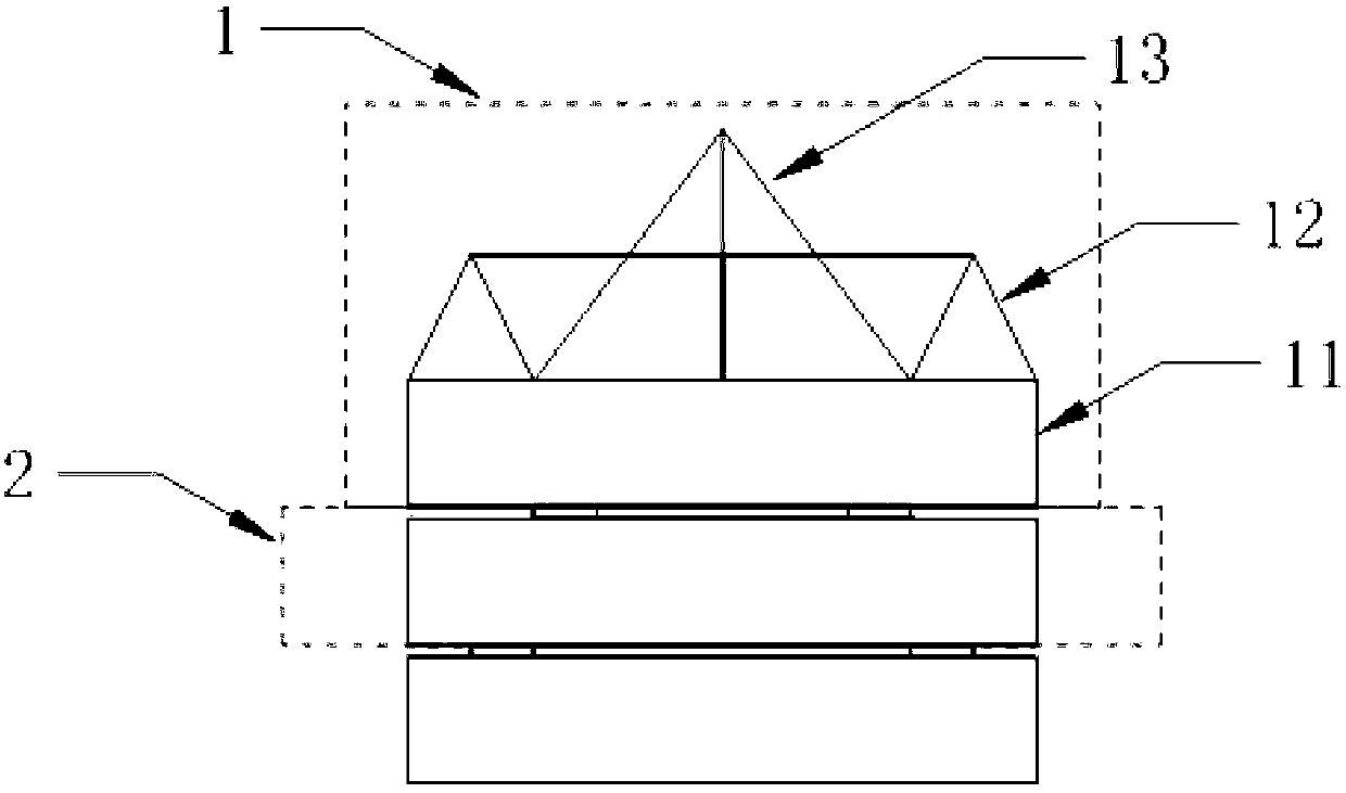
[0035] A thin composite multilayer bandgap microwave anechoic chamber wall lining, the thin composite multilayer bandgap microwave anechoic chamber wall lining is composed of wave-absorbing units arranged in an array, and the wave-absorbing units include one layer or stacked Multi-layer electromagnetic bandgap structure 2, on the electromagnetic bandgap structure of the uppermost layer, be provided with foam cone 1, described foam cone 1 comprises the foam base 11 that is arranged on the electromagnetic bandgap structure of uppermost layer, on foam base 11 is provided with conical foam 13. In this embodiment, a tapered foam ring 12 is provided on the foam base 11 , and the tapered foam 13 is disposed inside the tapered foam ring 12 . The height of the tapered foam 13 is great...


PUM


Abstract

A thin composite multiple-layer band gap microwave dark chamber wall body liner is composed of microwave absorbing units arranged according to arrays. Each microwave absorbing unit comprises one layer or multiple layers of overlaid magnetic band gap structures, wherein a foam pointed cone is arranged on the magnetic band gap structure on an upmost layer and comprises a foam base arranged on the magnetic band gap structure on the upmost layer, and conical foam is arranged on the foam base. In the thin composite multiple-layer band gap microwave dark chamber wall body liner, a conical foam ring is arranged on the foam base, and the conical foam is arranged in the conical foam ring. The height of the conical foam is larger than that of the conical foam ring. The number of multiple layers of overlaid magnetic band gap structures is two to four. A simulation result shows that at least -15dB of reflection coefficient can be achieved in a range from 0.6GHz to 3GHz under the condition that the overall liner thickness does not exceed 5cm.

Description

technical field [0001] The invention relates to the field of microwave anechoic chambers, and relates to a thin composite multilayer bandgap microwave anechoic chamber wall lining. The lining combines conical foam materials with a lossy electromagnetic bandgap structure to obtain good broadband absorption characteristics and reduce Material thickness and weight, suitable for applications in compact space such as small microwave anechoic chambers. Background technique [0002] Microwave anechoic chamber is a room specially designed to reduce electromagnetic wave reflection and external interference. It can better simulate free space test conditions and is mainly used for microwave measurements such as antennas, radar and electromagnetic interference characteristics. The key to the design of the microwave anechoic chamber is the performance of the wall lining material. The lining materials used are usually divided into two types, conical foam and ferrite tiles. Cone-shaped fo...

Claims


Application Information

Patent Timeline
IPC IPC(8): E04F13/075
Inventor 孙小菡段维嘉陈翰孙明明
Owner SOUTHEAST UNIV
Why Eureka
Try Eureka