
Engine timing cover lid structure

An engine and cover technology, applied in the direction of engine components, machines/engines, mechanical equipment, etc., can solve the problems of unfavorable parts generalization and platformization, affecting the insertion and removal of scales, increasing engine costs, etc., and eliminating the need for sealing O. ring, saving external space and saving cost

Inactive Publication Date: 2013-03-27
WUHU SHUNCHANG AUTO PARTS
View PDF8 Cites 3 Cited by
  • Summary
  • Abstract
  • Description
  • Claims
  • Application Information

AI Technical Summary

Problems solved by technology

[0003] The existing oil dipstick tubes mainly have the following disadvantages: 1. Generally, accessories, gear trains, intake and exhaust systems, cooling systems and booster systems need to be arranged around the engine. The curved arrangement makes the design of the scale tube more difficult. Sometimes the oil gauge tube is distorted to avoid interference with other surrounding parts, which easily affects the insertion and removal of the scale inside; 2. Because the same engine needs to be matched Different vehicles, and taking into account the situation of horizontal and vertical engines, in order to adapt to different vehicle front cabins, engine-related parts need to be modified. At this time, the oil dipstick tube often needs to be redesigned according to the new boundary, which will increase Increased engine cost, which is not conducive to the generalization and platformization of parts

Method used


Image

  • Engine timing cover lid structure
  • Engine timing cover lid structure
  • Engine timing cover lid structure

Examples


Embodiment Construction

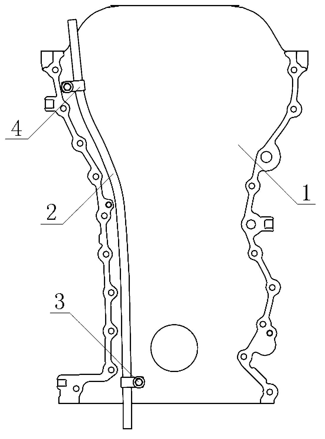
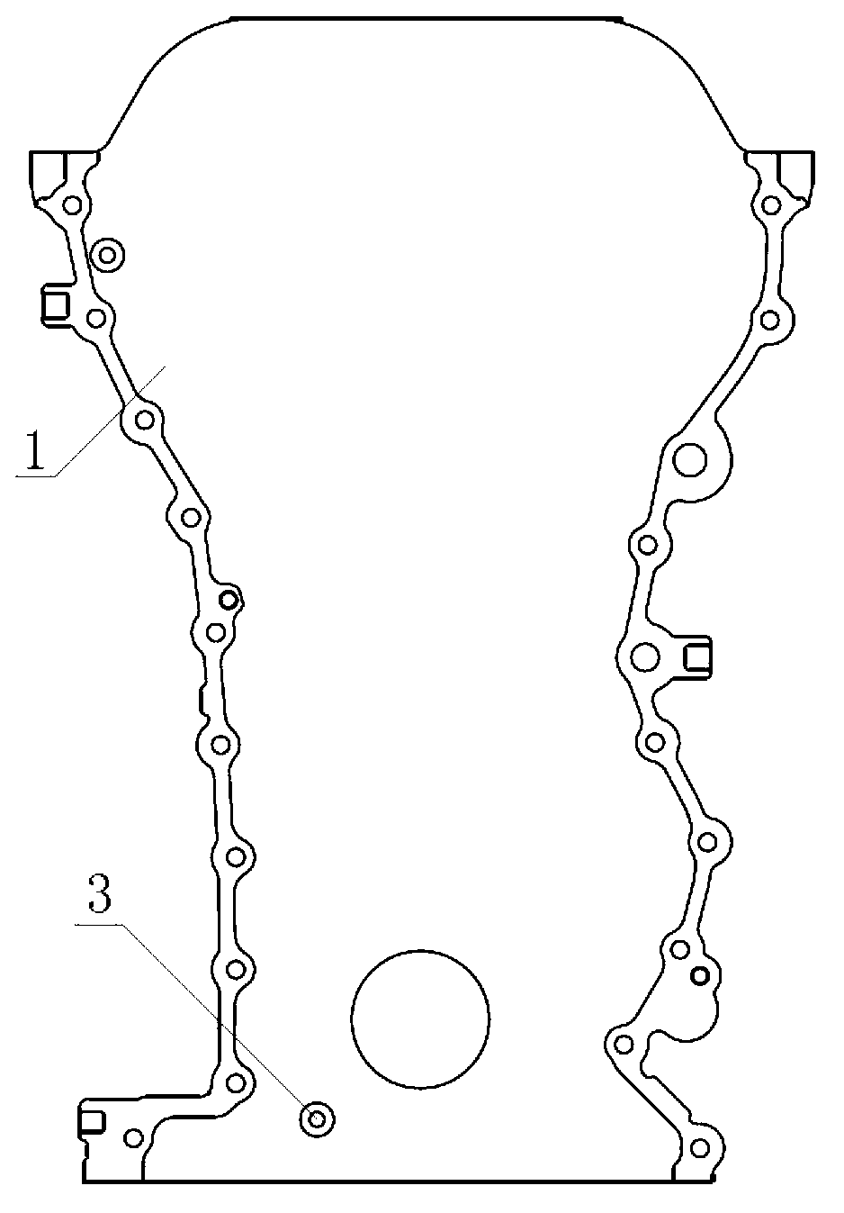
[0016] by Figure 1-3 The structure shown shows that this kind of engine timing cover includes a timing cover body 1 and an oil gauge tube 2 integrated with the timing cover body 1, and the timing cover body 1 is provided with an oil gauge tube The boss 3 of 2, the oil gauge tube 2 is provided with a welding bracket 4, and the welding bracket 4 is provided with a hole sleeved on the boss 3, the timing cover body 1 and the oil gauge tube 2 pass through the boss 3 and the hole There are two welding brackets 4, which are respectively located at the two ends of the oil gauge tube 2, and there are also two bosses 3, which are set on the timing cover body 1 at positions corresponding to the welding bracket 4.

[0017] The surface of the boss 3 needs to be machined to confirm that it has a good flatness, and the middle is punched and tapped. The position of the boss 3 needs to be arranged close to the side of the sealing surface of the timing cover body 1 and the cylinder block, so as ...


PUM


Abstract

The invention discloses an engine timing cover lid structure. The engine timing cover lid structure comprises a timing cover lid body (1) and an engine oil scale tube (2) which is integrated with the timing cover lid body (1), wherein a boss (3) for mounting the engine oil scale tube (2) is arranged on the timing cover lid body (1); a welding bracket (4) is arranged on the engine oil scale tube (2), and has a hole for being sleeved on the boss (3); and the timing cover lid body (1) and the engine oil scale tube (2) are assembled together through the boss (3) and the hole which are mutually matched. With the special structure, the engine timing cover lid structure, through scientific and skillful design, integrates the engine oil scale tube in the timing cover lid, in order to save the external space and to avoid the problem of interference of the peripheral pieces, so the engine is compact; and the engine oil scale tube is not influenced even if relative accessories of the engine are designed and modified to adapt to different finished automobiles or transverse and vertical modification.

Description

Technical field [0001] The invention relates to an engine timing cover structure, in particular to a timing cover structure integrated with an oil gauge tube. Background technique [0002] The oil gauge tube is generally installed on the cylinder, and its external shape is bent according to the layout of the engine. The oil gauge is inserted into it to detect the amount of engine oil and ensure that the amount of engine oil is within a proper range. [0003] Existing oil gauge pipes mainly have the following disadvantages: 1. Under normal circumstances, accessory gear trains, intake and exhaust systems, cooling systems, and supercharging systems need to be arranged around the engine. According to the location of the above accessories, find space to carry out the gauge pipe. The bending arrangement makes the design of the ruler tube more difficult. Sometimes the oil ruler tube has a large distortion in order to avoid interference with other surrounding parts, which easily affects th...

Claims


Application Information

Patent Timeline
IPC IPC(8): F02F7/00F01M11/12
Inventor 周军童培易刘萍方崇武
Owner WUHU SHUNCHANG AUTO PARTS
Learn More