
Direct-current high-voltage isolation sampling circuit

An isolated sampling, DC high voltage technology, applied in voltage/current isolation, measurement of current/voltage, measurement of electrical variables, etc., can solve problems such as port resources not meeting requirements, reduced A/D conversion accuracy, and limited role in improving accuracy. , to achieve the effect of reducing requirements, improving conversion performance and improving accuracy

Active Publication Date: 2013-03-27
EAST GRP CO LTD
View PDF12 Cites 12 Cited by
  • Summary
  • Abstract
  • Description
  • Claims
  • Application Information

AI Technical Summary

Problems solved by technology

For this kind of sampling circuit, on the one hand, due to the need for two-stage amplification, optocoupler isolation, filtering and protection, there are many intermediate processing links, which affect the accuracy of the sampling circuit and cannot reflect the small voltage fluctuations of high-voltage DC. Accuracy is generally replaced by devices with better performance, such as linear optocouplers, etc., which greatly increases the cost, but has a limited effect on the improvement of accuracy. If Hall elements are used, although the accuracy can be improved, the cost is high and requires Improving the dual power supply increases the complexity of the circuit; on the other hand, since the built-in A / D converter of the CPU is only 10 bits, if the A / D converter that comes with the CPU is only used for analog-to-digital conversion, the conversion accuracy is limited. Coupled with the interference of the previous processing link, the accuracy of A / D conversion is greatly reduced
In addition, due to the limited port resources of the CPU, when there are many sampling points, the port resources often cannot meet the demand

Method used


Image

  • Direct-current high-voltage isolation sampling circuit
  • Direct-current high-voltage isolation sampling circuit
  • Direct-current high-voltage isolation sampling circuit

Examples


Embodiment Construction

[0018] The present invention is further described in conjunction with the following examples.

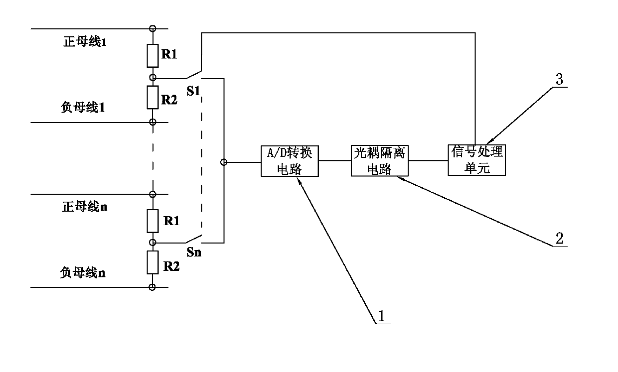
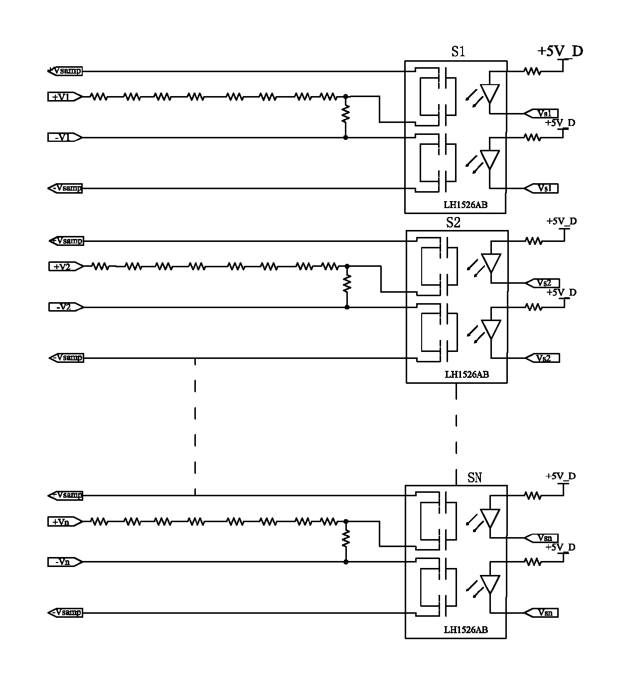
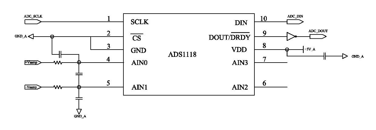
[0019] A specific embodiment of a multi-channel DC high-voltage sampling circuit of the present invention, as figure 1 As shown, it includes: a bus bar to be sampled, a voltage dividing sampling circuit is connected in series between the positive bus bar and the negative bus bar of the bus bar, and the described voltage dividing sampling circuit includes a series connection between the positive bus bar and the negative bus bar of the bus bar Between the voltage dividing resistor R1 and the voltage dividing resistor R2, the connection point of the voltage dividing resistor R1 and the voltage dividing resistor R2 is the output terminal. The purpose of voltage division sampling is realized in the simplest way. Of course, more electronic devices can be connected in series or in parallel between the positive bus and the negative bus of the bus to achieve the purpose of voltage division ...


PUM


Abstract

The invention relates to the technical field of direct-current sampling circuits, in particular to a direct-current high-voltage isolation sampling circuit which comprises buses to be sampled, an A / D (analog / digital) conversion circuit, an optical coupled isolation circuit and a signal processing unit. A voltage division sampling circuit is serially connected among the buses including positive buses and negative buses, an output end of the voltage division sampling circuit is connected with an input end of the A / D conversion circuit, an output end of the A / D conversion circuit is connected with an input end of an optical coupled isolator, and an output end of the optical coupled isolator is connected with the signal processing unit. Compared with the prior art, the direct-current high-voltage isolation sampling circuit has the advantages that signal processing links are few, and the sampling precision is improved; the A / D conversion precision is improved owing to the independent A / D conversion circuit; the direct-current high-voltage isolation sampling circuit is simplified, and the quantity of devices is lowered; and as signals are isolated, the requirement on an optical coupler is greatly lowered, and the cost of the direct-current high-voltage isolation sampling circuit is saved.

Description

technical field [0001] The invention relates to the technical field of DC sampling circuits, in particular to a DC high-voltage isolated sampling circuit. Background technique [0002] In various electronic devices, it is often necessary to perform voltage or current sampling on a bus with DC high voltage. In the prior art, the DC high-voltage sampling is usually divided into a voltage signal of tens of millivolts by a resistor first, and then a voltage signal of several volts is output by an isolated operational amplifier, and then filtered, amplified and protected, and finally sent to the CPU. A / D converter, so as to realize the isolation measurement and digital-to-analog conversion of high-voltage DC. At the same time, in order to improve the reliability and anti-interference ability of the DC system, the sampling circuit uses optocoupler isolation or voltage Hall isolation to electrically conduct the main circuit and the control circuit. isolation. For this kind of sam...

Claims


Application Information

Patent Timeline
IPC IPC(8): G01R19/00G01R15/22
Inventor 王长华梁云龙邵攀峰张士兵
Owner EAST GRP CO LTD
Learn More