Module personalized parameter transmission method and system

A transmission system and parameter technology, applied in data processing applications, electrical digital data processing, digital computer components, etc., can solve the problems of difficult control of OTP programming failure rate, insufficient OTP storage space, etc., to avoid data failure , cost reduction, and yield improvement

Active Publication Date: 2016-06-08
NINGBO SUNNY OPOTECH CO LTD
View PDF10 Cites 0 Cited by
  • Summary
  • Abstract
  • Description
  • Claims
  • Application Information

AI Technical Summary

Problems solved by technology

[0003] The main purpose of the present invention is to solve the OTP storage space deficiency or the OTP programming bad rate is difficult to control and more flexibly define the consistent problem of high pixel module, the solution is as follows:

Method used


Image

  • Module personalized parameter transmission method and system

Examples


Embodiment Construction

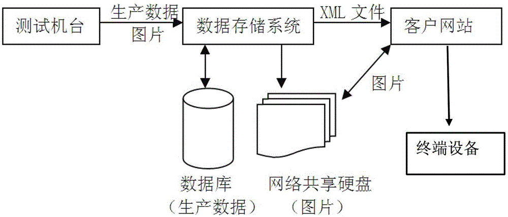
[0022] figure 1 It is a schematic diagram of the embodiment of the present invention. As shown in the figure, the module manufacturer first establishes a data storage system, which includes a test station, a database and a network shared hard disk. Regarding the storage space, it is stored in the form of a server. Store data in the form of a database. In theory, such a storage space can be expanded infinitely, and can continuously meet the different needs of different customers.

[0023] Each cameramodule has a unique fuseID to identify different modules. When the module manufacturer produces, the test data and pictures (as mentioned above) generated by each camera module are named and stored on the server with fuseID. The storage speed of this method will also be faster. After the data is generated, it only needs to be saved to the server. It does not need to be burned to OTP / EEPROM, and the module will not be scrapped due to burning failure.

[0024] When the client needs ...


PUM


Abstract

A method for passing personalized parameters of a module, comprising the following steps: 1) using a reading device to read unique product IDs of module products; 2) confirming corresponding personalized parameters of a module according to the product IDs; and 3) passing the personalized parameters of the module to a client using an information passing device. The method can overcome the defects of small storage space, slow storage speed and small storage data amount in the traditional storage solution, and further meet the requirements of high-end customers for image quality, thereby reducing costs, and improving the product yield.

Description

technical field [0001] The invention relates to a method for acquiring OTP data of a high-pixel module, in particular to a method and a system for transmitting module personalized parameters. Background technique [0002] At present, when camera module manufacturers produce camera modules, they generate some personalized parameters / data according to the characteristics of each module, such as moduleID, LensID, motor ID, AWB, shading, and AF, etc., which need to be set in the back-end system. At present, the OTP / EERPOM scheme is adopted, that is, the data generated by each camera module is stored in the OTP / EERPOM. When the mobile phone uses the camera module, it first reads the data from the OTP / EERPOM, and then applies it to the sensor. The purpose of this is to allow the back-end system to read out a set of personalized parameters of each camera module and perform targeted settings, which can greatly improve the consistency of the modules. The disadvantage is that the st...

Claims


Application Information

Patent Timeline
Patent Type & Authority Patents(China)
IPC IPC(8): G06F15/177G06K7/10
CPCG06Q10/06
Inventor 徐永松
Owner NINGBO SUNNY OPOTECH CO LTD
Why Eureka
Try Eureka