
Non-drain differential signal transmission cable and ground connection structure thereof

A differential signal and grounding structure technology, applied in the direction of insulated cables, cables, circuits, etc., can solve problems such as installation density restrictions, and achieve the effect of increasing installation density

Inactive Publication Date: 2013-03-27
HITACHI METALS LTD
View PDF4 Cites 15 Cited by
  • Summary
  • Abstract
  • Description
  • Claims
  • Application Information

AI Technical Summary

Problems solved by technology

[0012] Therefore, when mounting a plurality of cables 160 for differential signal transmission, the arrangement interval of cables 160 for differential signal transmission must conform to the width of the ground pad 170, so that the mounting density is limited.

Method used


Image

  • Non-drain differential signal transmission cable and ground connection structure thereof
  • Non-drain differential signal transmission cable and ground connection structure thereof
  • Non-drain differential signal transmission cable and ground connection structure thereof

Examples


Embodiment Construction

[0052] Hereinafter, best embodiments of the present invention will be described with reference to the drawings.

[0053] First, the drainless differential signal transmission cable according to the first embodiment will be described.

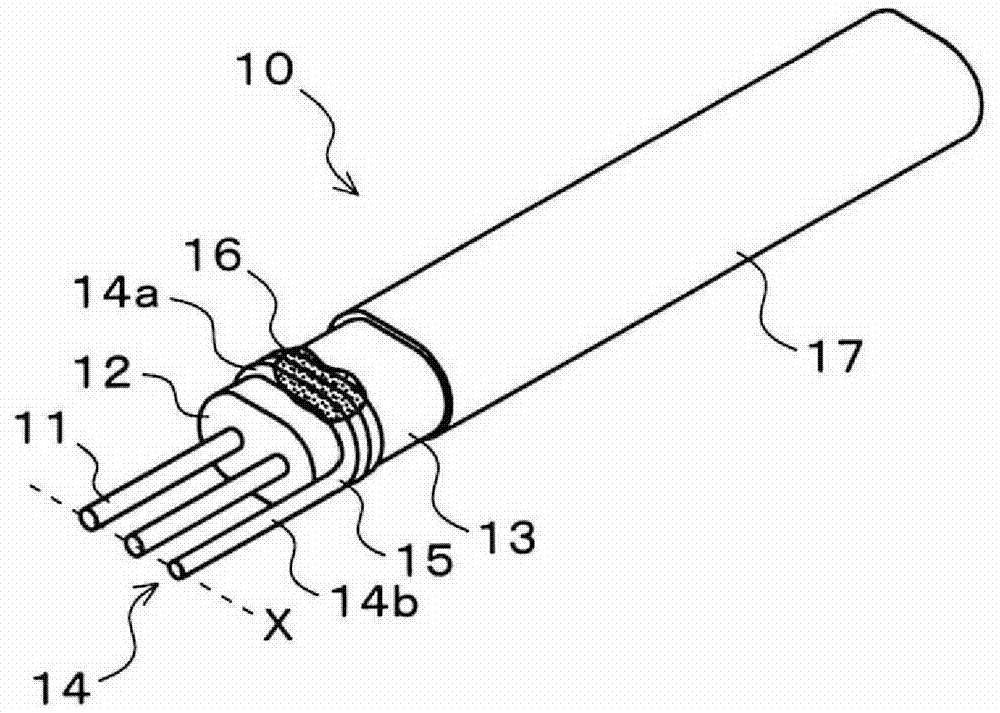
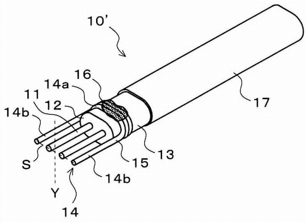
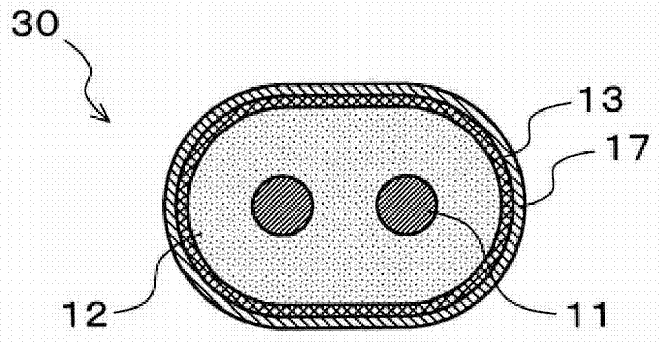
[0054] Such as figure 1 As shown, the drainless differential signal transmission cable 10 of the first embodiment is characterized in that it includes: a pair of signal line conductors 11 arranged in parallel; an insulator 12 provided around the pair of signal line conductors 11; The shield conductor 13 around the insulator 12; and the metal wire 15 is used to solder the shield conductor 13 to the ground (for example, a ground pad described later is mentioned, but other terminals, etc. ), the ends of a pair of signal line conductors 11 are exposed from the insulator 12 and the shield conductor 13, and the ground needle 14 has a winding portion 14a in which a part of the metal wire 15 is wound around the shield conductor 13, and a metal The en...


PUM

PropertyMeasurementUnit
impedanceaaaaaaaaaa

Abstract

The invention provides a non-drain differential signal transmission cable and ground connection structure thereof. it is possible to prevent to prevent melting or evaporation of the shield conductor and deformation or melting of the insulation during the soldering work, and also possible to improve a package density. A non-drain differential signal transmission cable 10 includes a pair of signal conductors 11 aligned in parallel, an insulation 12 around the pair of signal conductors 11, a shield conductor 13 around the insulation 12, and a ground connecting pin 14 to electrically connect the shield conductor 13 to a ground, the ground connecting pin 14 including a wire 15. An end portion of the pair of signal conductors 11 is exposed to the outside from the insulation 12 and the shield conductor 13. The ground connecting pin 14 includes a winding portion 14a wound around the shield conductor 13, and a pin portion 14b which is formed by the end portion of a metallic wire 15 and having a needle shape.

Description

technical field [0001] The invention relates to a cable for differential signal transmission without drain wire and its grounding structure. Background technique [0002] In machines such as servers, routers, and memory products that process high-speed digital signals of several Gbit / s or more, differential signal transmission is used for signal transmission between machines or between substrates (circuit boards) in the machine. [0003] The so-called differential signal refers to the use of two paired signal line conductors to transmit signals whose phases are reversed by 180 degrees, and to synthesize and output the differences of the signals received at the receiving side. Since the currents flowing through the pair of signal line conductors flow in opposite directions to each other, electromagnetic waves radiated from the transmission line are small. In addition, since external noise is superimposed on the pair of signal line conductors equally, the influence of the noi...

Claims


Application Information

Patent Timeline
Patent Type & Authority Applications(China)
IPC IPC(8): H01B7/00H01B7/17
CPCH01R4/66H01R13/65915
Inventor 南亩秀树杉山刚博
Owner HITACHI METALS LTD
Learn More