
Electromagnetic vibration power generation device

An electromagnetic vibration and power generation device technology, applied in the direction of electromechanical devices, electrical components, etc., can solve the problems of low power generation efficiency and low magnetic circuit utilization rate, and achieve the goal of improving magnetic circuit utilization rate, improving efficiency, and reasonable structural design Effect

Active Publication Date: 2015-03-04
SHANDONG SHENGRUN AUTOMOBILE
View PDF8 Cites 1 Cited by
  • Summary
  • Abstract
  • Description
  • Claims
  • Application Information

AI Technical Summary

Problems solved by technology

[0005] In order to overcome the shortcomings of the existing electromagnetic vibration power generation device, such as low magnetic circuit utilization rate and low power generation efficiency, the present invention provides an electromagnetic vibration power generation device with small vibration resistance, high magnetic circuit utilization rate and high power generation efficiency

Method used


Image

  • Electromagnetic vibration power generation device
  • Electromagnetic vibration power generation device
  • Electromagnetic vibration power generation device

Examples


Embodiment Construction

[0028] The present invention will be further described below in conjunction with the accompanying drawings.

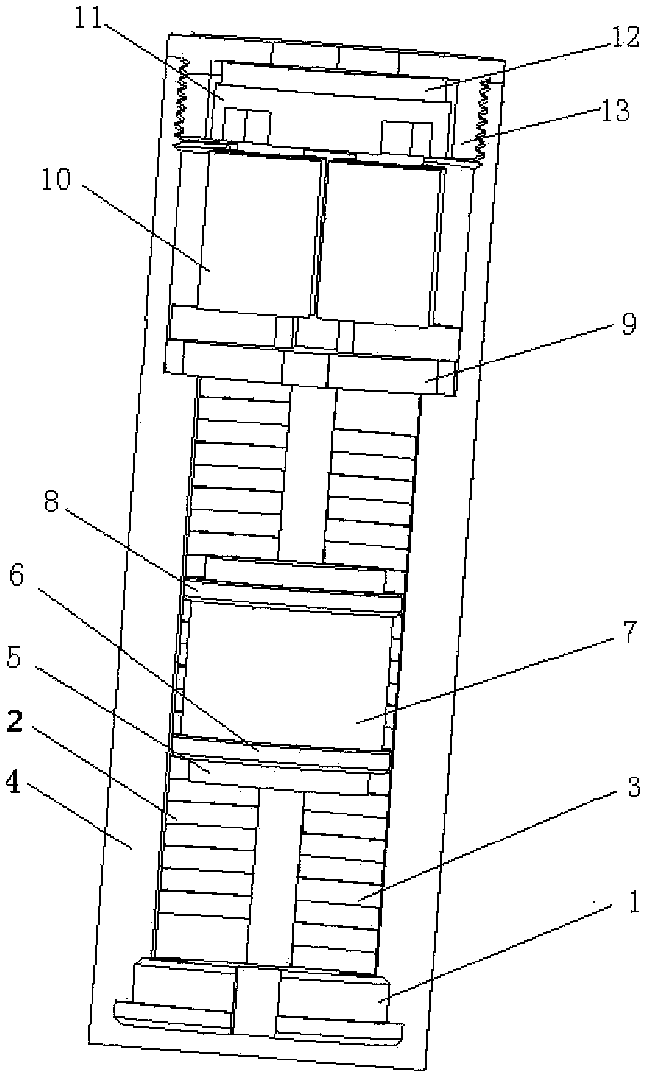
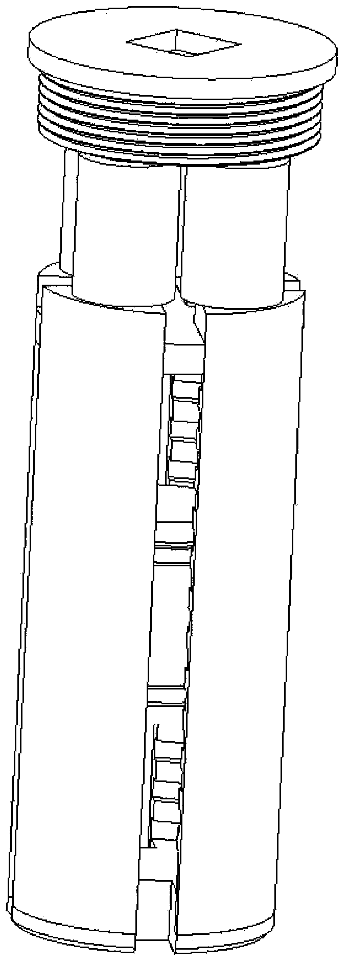
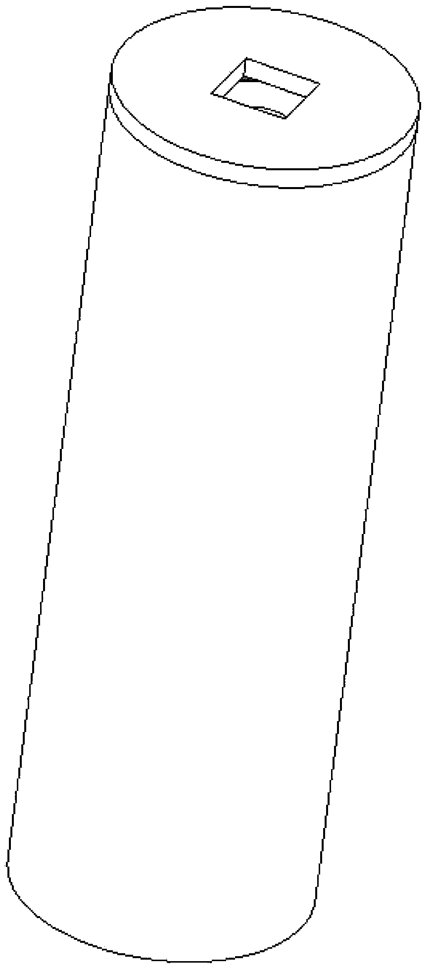
[0029] refer to Figure 1 to Figure 9 , an electromagnetic vibration power generation device, including a lower yoke bracket 1, two left and right yokes and two front and rear yokes 3, a shell 4, an upper and lower buffer 5, a lower armature 6, a permanent magnet 7, an upper armature 8, and an upper magnet Yoke bracket 9, induction coil 10, yoke top 11, rubber ring 12, top cover 13. The shell 4 is made of aluminum material and is cylindrical with a bottom, and four guide rails are evenly distributed on its inner wall; the lower yoke bracket 1 is made of aluminum material and is located at the bottom of the shell 4 , the lower yoke bracket 1 includes upper and lower parts, which are respectively composed of a middle cylinder and four fan-shaped blocks, and the fan-shaped block and the upper guide rail of the shell are mutually locked as the circumferential positioning ...


PUM


Abstract

An electromagnetic vibration power generation device comprises a casing, wherein a vibrator capable of vertically sliding is arranged in the casing. The vibration power generation device further comprises four induction coils, a front magnet yoke, a back magnet yoke, a left magnet yoke, a right magnet yoke, an upper magnet yoke support and a lower magnet yoke support. The casing is a cylinder with a bottom and is made of non-magnetic materials, four guide rails are evenly distributed on the inner lateral wall of the cylinder, the vibrator can be slidingly arranged on the guide rails, and the smallest dimension of each guide rail in the radial direction is smaller than the radius of the top of each protruded square tooth on each magnet yoke. The lower magnet yoke support, the magnet yokes, the vibrator, the upper magnet yoke support, the induction coils and yoke tops are arranged in the casing from bottom to top in sequence. The four magnet yokes are made of soft magnetic materials and symmetrically distributed in an adjacent mode along the circumferential direction of a cavity of the casing, the two magnet yokes at opposite positions are completely identical, and the square teeth of the adjacent magnet yokes are distributed in a convex-concave stagger mode. The electromagnetic vibration power generation device is small in vibration resistance, high in magnetic circuit utilization rate and high in power generation efficiency.

Description

technical field [0001] The invention relates to a vibration power generating device. Background technique [0002] In recent years, people's interest in new environmentally friendly power supply methods has been increasing. Energy harvesting technology is one of the most promising methods to replace traditional power supply methods. It has attracted the attention of many scholars. For example, it can collect magnetic energy in the environment for wireless sensor network nodes. use. Vibration is ubiquitous in nature, such as waves fluctuating, people vibrating up and down when walking, cars bumping, branches swaying with the wind, etc. The vibration energy is usually ignored or absorbed by shock absorbers and other equipment. If the energy generated by vibration is collected and replaced by batteries to power some low-power devices such as micro-sensor network nodes or Internet of Things nodes, it will not only reduce the environmental pollution caused by batteries, but also...

Claims


Application Information

Patent Timeline
Patent Type & Authority Patents(China)
IPC IPC(8): H02K35/02
Inventor 张端林晨宽何熊熊
Owner SHANDONG SHENGRUN AUTOMOBILE
Learn More