Motor rotor angle predicting device and motor rotor angle predicting method

A technology of motor rotors and predictive devices, applied in the direction of electronic commutators, etc., can solve the problems of complex installation, unadjustable measurement accuracy, and high cost, and achieve the effects of strong real-time performance, fast calculation speed, and low cost

Inactive Publication Date: 2013-03-27
常州科教城新能源汽车工程技术研究院
View PDF4 Cites 11 Cited by
  • Summary
  • Abstract
  • Description
  • Claims
  • Application Information

AI Technical Summary

Problems solved by technology

Although the existing technology has the advantages of reading the coordinate value and counting without accumulative error, the response time of the detector and the circuit does not need to be considered when rotating, the reliability is high, and it will not be affected by interruption interference, but there is also a measurement accuracy. Disadvantages such as non-adjustable, complicated installation and high cost

Method used


Image

  • Motor rotor angle predicting device and motor rotor angle predicting method

Examples


Embodiment 1

[0023] This embodiment includes a Hall sensor 1 and a micro control unit.

[0024] The Hall sensor 1 is electrically connected with the micro control unit; there are three Hall sensors 1, and they are evenly arranged around the motor rotor; the micro control unit is provided with a counting device.

[0025] The method for predicting the rotor angle of the motor using the motor rotor angle prediction device comprises the following steps:

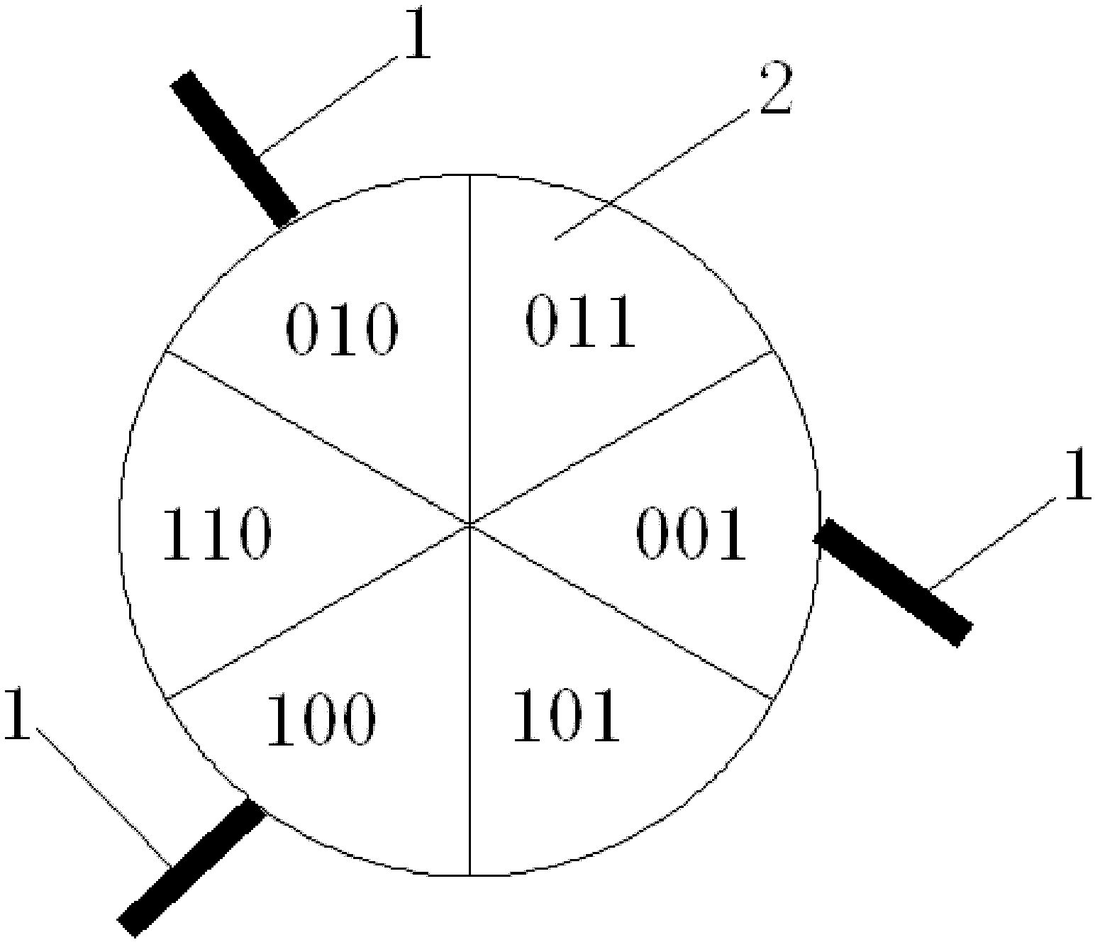
[0026] ① According to the installation position of the motor Hall sensor 1, the interval of the motor rotor represented by the different combinations of Hall signals is preset, specifically: three Hall sensors 1 divide the circle 2 where the entire motor rotor is located into six Each interval corresponds to a combination of Hall signals.

[0027] 2. Establish a two-dimensional array storing the rotor angle value of the motor according to the interval of the rotor obtained in step 1; one of the dimensions of the two-dimensional array is dete...


PUM


Abstract

The invention discloses a motor rotor angle predicting device which comprises a plurality of Hall sensors and a micro-control unit. The Hall sensors are electrically connected with the micro-control unit and evenly distributed on the periphery of a motor rotor. A counting device is disposed in the micro-control unit. The motor rotor angle predicting device can calculate current motor rotor angles in real time, provides an excellent motor rotor angle solution for motor control algorithm, is suitable for state detection of a motor controller and a motor, improves efficiency of the motor controller, and guarantees stability of the motor. In addition, the motor rotor angle predicting device is low in cost, highly practical and precision-adjustable.

Description

technical field [0001] The invention relates to a motor rotor angle prediction device and a prediction method thereof. Background technique [0002] The traditional method of predicting the rotor angle of a motor is realized through an encoder disc. The most common disc-type optical encoder is an absolute value angle encoder, which uses digital encoding to represent the displacement from the origin, also That is to engrave scale marks on the scale, and when the auxiliary scale stops moving, use the reading symbols to measure the position of the scale, so as to realize the detection of the motor rotor angle. Although the existing technology has the advantages of reading the coordinate value and counting without accumulative errors, the response time of the detector and the circuit does not need to be considered when rotating, the reliability is high, and it will not be affected by interruption interference, but there is also a measurement accuracy. Disadvantages such as non-...

Claims


Application Information

Patent Timeline
Patent Type & Authority Applications(China)
IPC IPC(8): H02P6/16
Inventor 王瑛周大为
Owner 常州科教城新能源汽车工程技术研究院
Why Eureka
Try Eureka