
Common standard case for folding electronic equipment

A kind of electronic equipment and folding technology, which is applied in the direction of electrical equipment shell/cabinet/drawer, electrical components, magnetic field/electric field shielding, etc. The circuit modules do not have independence, and the folding and open chassis structure has not been realized, so as to achieve the effect of conveniently improving the design space, facilitating improvement and adapting to the design, and enhancing independence

Inactive Publication Date: 2015-11-18
10TH RES INST OF CETC
View PDF5 Cites 0 Cited by
  • Summary
  • Abstract
  • Description
  • Claims
  • Application Information

AI Technical Summary

Problems solved by technology

The specific manifestations are: the size and installation interface of these chassis are designed according to the specific equipment and installation requirements, and do not meet the standard chassis requirements of the MCU size series stipulated in the HB7390-96, ARINC600 specifications and other standards; the chassis design is closely integrated with the internal circuits and modules, and the chassis and circuit modules are not independent, and do not meet the requirements of generalization and combination; the chassis only has a single size specification, and has not been serialized; the real folding and open chassis structure has not been realized, and the module installation, use, and maintenance performance are poor ;The chassis is mainly aimed at civilian products, and its structural rigidity, electromagnetic shielding performance, and environmental adaptability are not suitable for the harsh requirements of military, airborne and other users and platforms on the chassis.

Method used


Image

  • Common standard case for folding electronic equipment
  • Common standard case for folding electronic equipment
  • Common standard case for folding electronic equipment

Examples


other Embodiment approach

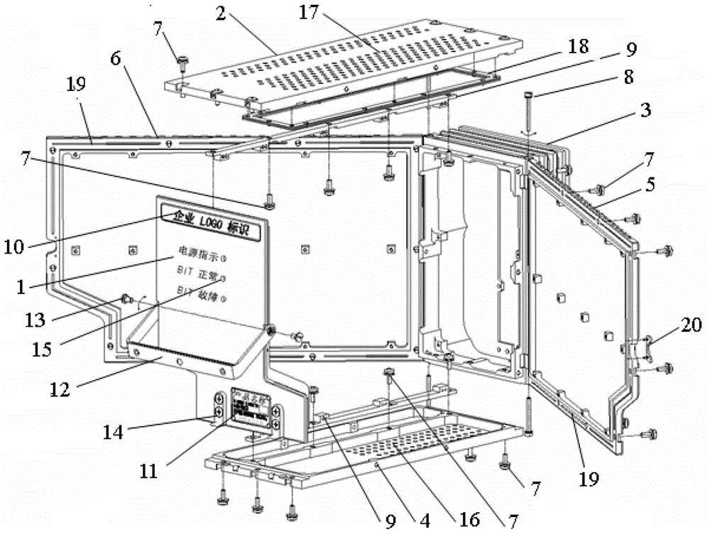
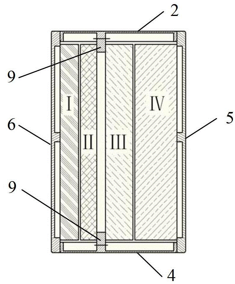
[0034] other implementations. In addition to the above-mentioned specific implementation methods, the cabinet can also expand the scope of use by changing the design scheme of some components. Typically, the ventilation and heat dissipation hole arrays on the top plate 2 and the bottom plate 4 of the case are eliminated to form a natural heat dissipation case, and the left and right side doors 5 and 6 of the case are integrated with the functional modules I and IV to form a composite case, etc.


PUM


Abstract

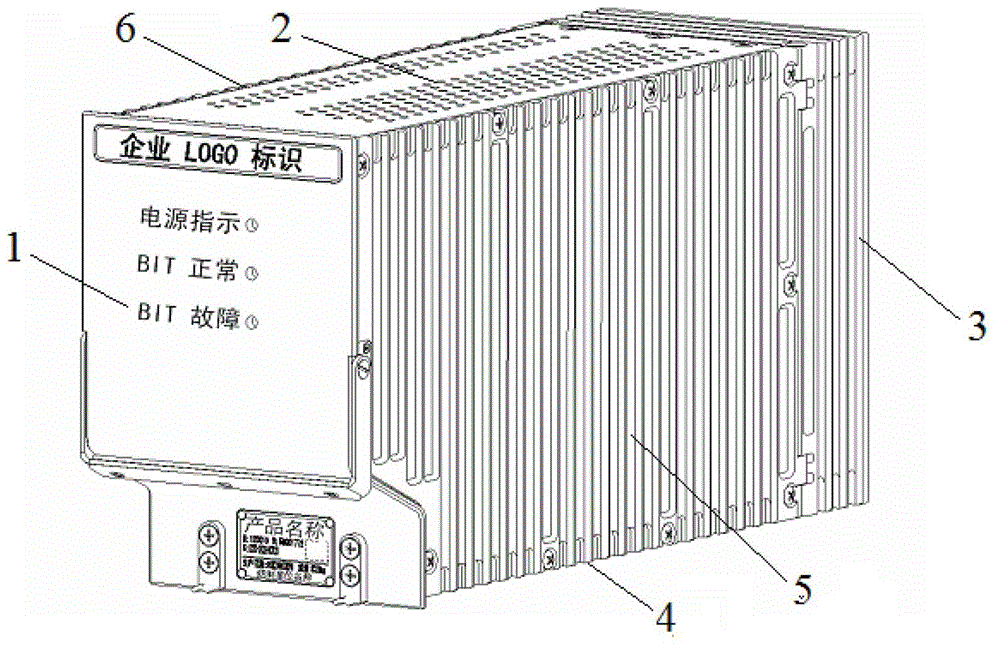
The invention provides a folding general case for electronic devices. The general case for the electronic devices which are LRUs (line replaceable units) can be used for various military and civil purposes, is applicable to various platform conditions and belongs to an MCU (modular concept unit) dimension series with characteristics of standardization, generalization, serialization and modularization. The technical scheme includes that the folding general case comprises a face plate (1), a top plate (2), a rear frame (3) and a bottom plate (4) which are longitudinally fixedly connected with one another by screw assemblies (7) to form a rectangular case frame, left and right side doors (5 and 6) which can be folded and unfolded are mounted on two side surfaces of the rear frame by rotary shaft and screw combinations (8) in a mirror symmetry manner, function modules I and IV can be mounted on the left and right side doors, function modules II and III can be mounted between the top plate and the bottom plate, and an interface module V can be mounted in the rear frame of the case; environmental control cooling air is filled into the case from air inlets (16) at the bottom of the case and is exhausted from air outlets (17) on the top of the case; and a metal wire shielding net assembly (18) is mounted on the inner side surface of an air outlet region of the top plate of the case.

Description

technical field [0001] The invention relates to a universal standard case mainly used for aviation and communication electronic equipment. Background technique [0002] The electronic equipment chassis is a basic structure that reasonably assembles various electronic components, components, modules and mechanical parts inside the equipment into an organic whole to protect it from various complex environmental influences and interferences and ensure the realization of electrical performance. As a modern high-tech product, the electronic equipment case is no longer a simple concept of equipment casing and mechanical installation support, but a comprehensive technology that reflects the overall design concept of electronic equipment as the basic design content to meet the equipment function and use environment requirements. Foreign developed countries, especially Europe and the United States, have long implemented the standardization and serialization design of military and civ...

Claims


Application Information

Patent Timeline
Patent Type & Authority Patents(China)
IPC IPC(8): H05K5/00H05K7/20H05K9/00
Inventor 熊长武李响
Owner 10TH RES INST OF CETC
Learn More