Reciprocating compressor with high pressure storage vessel let down for cng station and refueling motor vehicles

一种存储容器、压缩机的技术,应用在压缩机领域,能够解决能效低等问题

Inactive Publication Date: 2013-03-27
CLEAN ENERGY FUELS CORP
View PDF6 Cites 0 Cited by
  • Summary
  • Abstract
  • Description
  • Claims
  • Application Information

AI Technical Summary

Problems solved by technology

The design is very energy inefficient because the air pressure is reduced before repressurization in the compressor

Method used


Image

  • Reciprocating compressor with high pressure storage vessel let down for cng station and refueling motor vehicles
  • Reciprocating compressor with high pressure storage vessel let down for cng station and refueling motor vehicles

Examples


Embodiment Construction

[0019] In the following paragraphs, the present invention is described in detail by way of example with reference to the accompanying drawings. Throughout the specification, the preferred embodiment and examples shown should be regarded as exemplifications, not limitations of the invention. As used herein, "the invention" refers to any embodiment of the invention described herein, and any equivalents thereof. Furthermore, reference throughout the text to various feature(s) of the "present invention" does not mean that all claimed embodiments or methods must include the referenced feature(s).

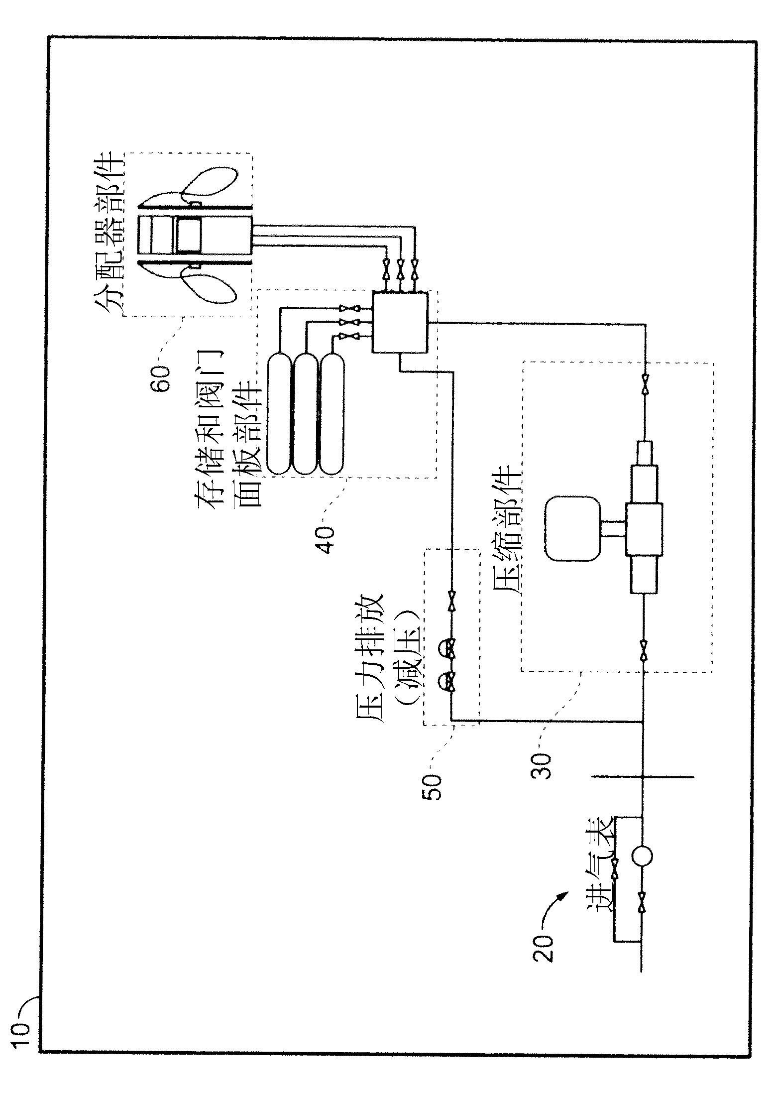
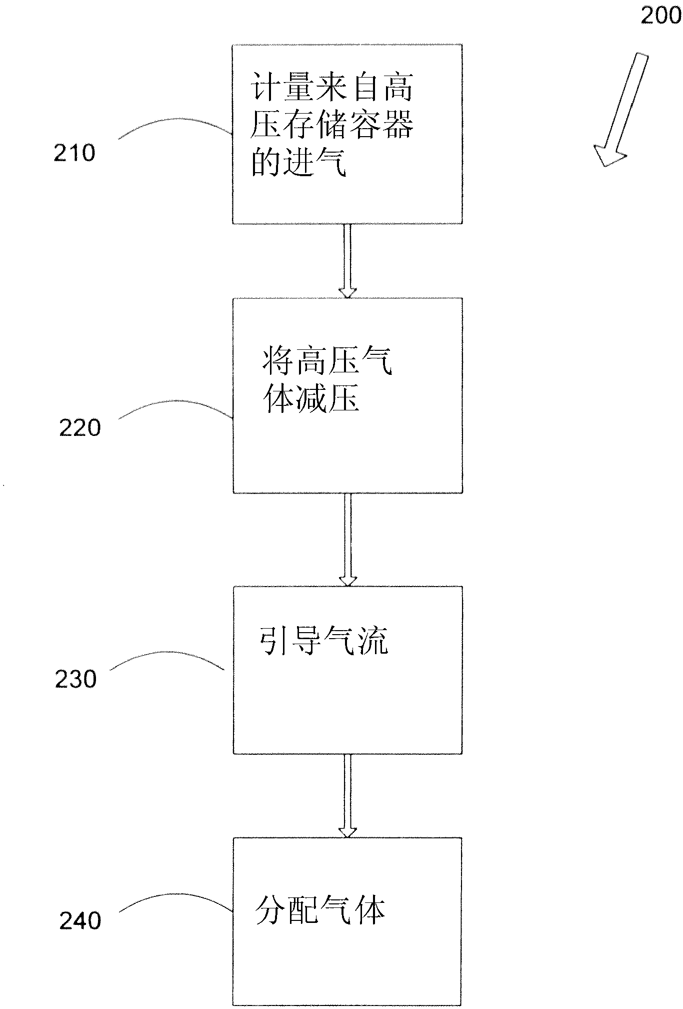
[0020] Embodiments of the present invention are directed to a reciprocating compressor with a high pressure storage vessel that decompresses a CNG station for refueling a motor vehicle, wherein the CNG station is designed to utilize intake air from a local gas company. A CNG station has the ability to increase and adjust its flow capacity by supplementing the intake air with a pressure ...


PUM


Abstract

Embodiments of the present invention are directed toward a reciprocating compressor having a high pressure storage vessel let down for a CNG station for refueling motor vehicles, wherein the CNG station design utilizes inlet gas from a local gas utility. By supplementing the inlet gas with a pressure let down in order to de-pressurize the gas from a high-pressure storage vessel, the CNG station has the ability to increase and adjust its flow capacity.

Description

[0001] References to related applications [0002] This application claims the benefit of US Provisional Patent Application 61 / 353625, filed June 10, 2010, the entire contents of which are hereby incorporated by reference. technical field [0003] The present invention relates generally to compressors for compressed natural gas (CNG) stations used to refuel motor vehicles, and more particularly to reciprocating compressors having a high pressure storage vessel that depressurizes the CNG station for supplying Motor vehicle refueling. Background technique [0004] Most conventional CNG plants are custom designed for specific site conditions and must operate within predetermined inlet pressure and flow ranges. These gas stations typically take a long time to build, and because they are designed to meet specific site conditions, the flow capacity is limited by the inlet pressure available from the local gas company. According to other known CNG designs, air inlet regulators ar...

Claims


Application Information

Patent Timeline
Patent Type & Authority Applications(China)
IPC IPC(8): B65B1/20
CPCB65B1/20F17C2221/033F17C2223/0123F17C2223/036F17C2225/0123F17C2225/036F17C2227/0164F17C2227/0185F17C2250/0626F17C2265/065F17C2270/0178F17C5/06
Inventor D·丁M·普拉塔
Owner CLEAN ENERGY FUELS CORP
Why Eureka
Try Eureka