Silencer for a multi-leaf spring

A technology of muffler and laminated plate, applied in the direction of spring/shock absorber, leaf spring, vehicle spring, etc., can solve the problems of complex manufacturing process and large number of parts, etc.

Active Publication Date: 2013-03-27
NHK SPRING CO LTD
View PDF8 Cites 1 Cited by
  • Summary
  • Abstract
  • Description
  • Claims
  • Application Information

AI Technical Summary

Problems solved by technology

[0010] However, in the technology of Patent Document 1, it is necessary to install the reinforcement fitting inside the muffler as a separate part, and the manufacturing process becomes complicated.
In addition, in the technique of Patent Document 2, since two mufflers are provided between the leaf springs, the number of parts increases.
In addition, in order to achieve both the improvement of the strength of the protrusion and the prevention of abnormal noise, the above-mentioned problems occur at the same time.

Method used


Image

  • Silencer for a multi-leaf spring
  • Silencer for a multi-leaf spring
  • Silencer for a multi-leaf spring

Examples


Embodiment Construction

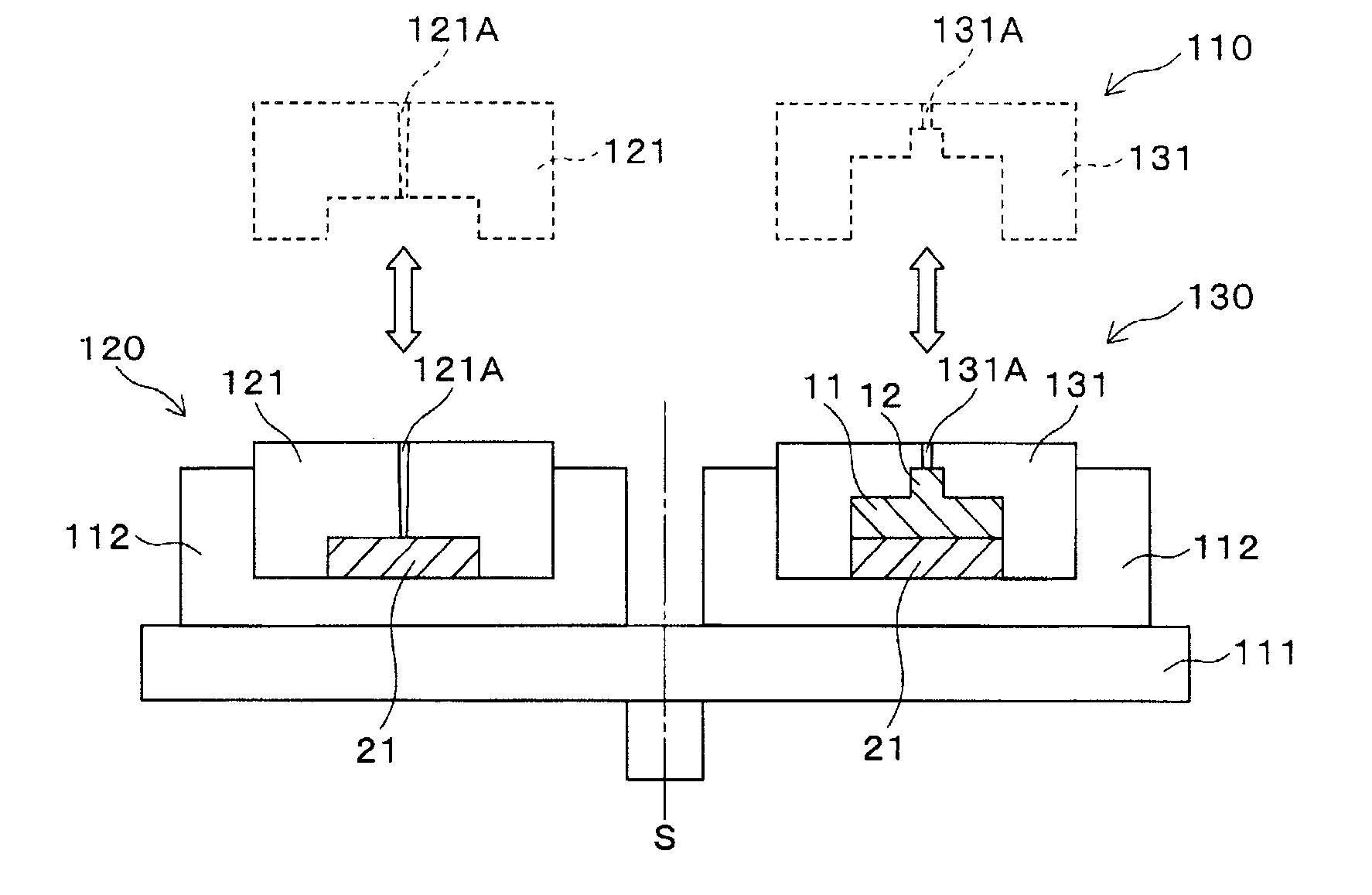
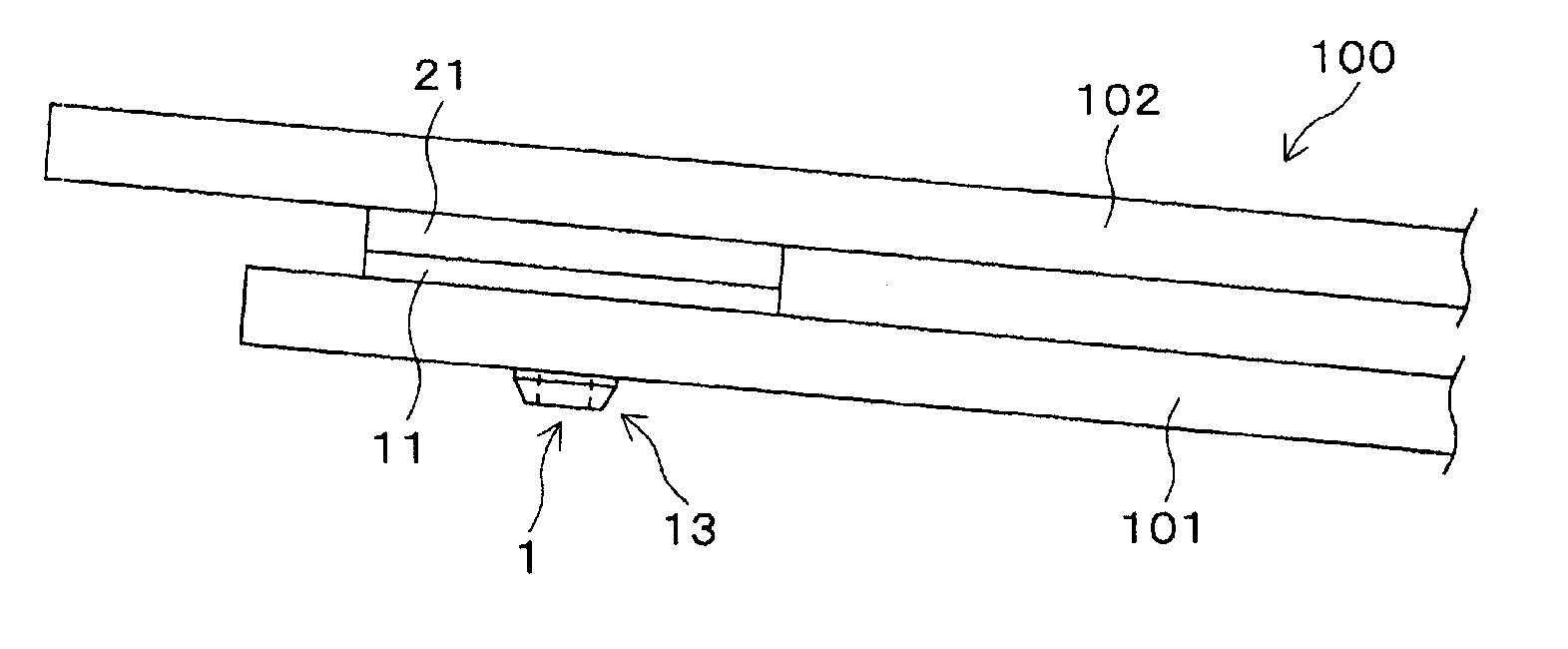
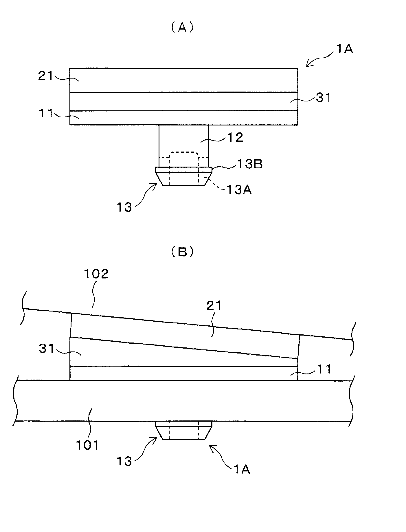
[0039] Embodiments of the present invention will be described below with reference to the drawings. figure 1 A side view showing a schematic configuration of a laminated leaf spring muffler 1 (hereinafter, muffler 1 ) according to an embodiment of the present invention is arranged between leaf springs 101 and 102 of a laminated leaf spring 100 . figure 2 means as figure 1 The shown structure of the muffler 1, (A) is a side view, (B) is an enlarged side sectional view, (C) is a plan view. figure 2 (B) is figure 2 (C) Side sectional view of line 1B-1B. The laminated leaf spring 100 is a general laminated leaf spring, in figure 1 In , only the left end portion of the laminated leaf spring 100 is shown. The muffler 1 is arranged between the ends of the leaf springs 101 and 102 of the laminated leaf spring 100 . figure 2 (C) is a plan view seen from the protrusion 12 side of the muffler 1 .

[0040] The muffler 1 has, for example, a two-layer structure having a fixed laye...


PUM


Abstract

Disclosed is a silencer for a multi-leaf spring whereby both the strength of a protruding part is increased and anomalous noises are prevented, and a component count is reduced due to structural simplification and increased ease of manufacture. Said silencer (1), which is disposed between the ends of leaf springs (101 and 102) in a multi-leaf spring (100), has a two-layer structure comprising a fixed layer (11) and a sliding layer (21) formed as a single unit. The fixed layer (11) has a protruding part (12) with an engagement part (13) formed in the tip thereof. The fixed layer (11), which is affixed to a fixed-side leaf spring (101), has a higher tensile strength than the sliding layer (21). The sliding layer (21), which abuts against a sliding-side leaf spring (102), is harder than the fixed layer (11). The protruding part (12) of the fixed layer (11) can exhibit sufficient strength with respect to shear forces. The sliding layer (21) is not prone to anomalous noises and can even minimize anomalous noises when a load-transmission part of the end of the sliding-side leaf spring (102) makes off-center contact.

Description

technical field [0001] The present invention relates to a muffler for laminated leaf springs, and more particularly to an improvement in the muffler structure for improving various characteristics. Background technique [0002] In a laminated leaf spring used in a vehicle suspension such as an automobile, a plurality of leaf springs are stacked, and U-shaped bolts sandwiching the leaf springs are assembled from, for example, the upper side of the central portion in the longitudinal direction. In this case, for example, a spacer is provided between the leaf springs in the center portion in the longitudinal direction, for example, a spacer is provided between the uppermost leaf spring and the U-bolt. In the laminated leaf spring, both ends of the U-bolt are fastened to a mandrel arranged below the lowermost leaf spring. [0003] In such a laminated leaf spring, a muffler is provided between both ends of the leaf springs in the longitudinal direction. The muffler is used to p...

Claims


Application Information

Patent Timeline
Patent Type & Authority Applications(China)
IPC IPC(8): F16F1/20B60G11/02
CPCB60G2202/11B60G11/02F16F1/20B60G11/38F16F2238/022
Inventor 矢野纯一佐藤尚志坂出宪俊
Owner NHK SPRING CO LTD
Why Eureka
Try Eureka