Liquid pressure generating apparatus and driving apparatus

A technology for generating devices and driving devices, which is applied in the directions of transmission devices, transmission device control, and pneumatic power devices, etc., and can solve the problems of unmentioned pump drive shaft support accuracy, unmentioned pump drive shaft, and unfound pump drive shaft support Accuracy and other issues

Active Publication Date: 2013-03-27
AISIN AW CO LTD +2
View PDF7 Cites 1 Cited by
  • Summary
  • Abstract
  • Description
  • Claims
  • Application Information

AI Technical Summary

Problems solved by technology

[0005] However, in the above-mentioned Patent Document 1 and Patent Document 2, there is no mention of the support accuracy for the pump drive shaft.
Therefore, in the above-mentioned Patent Document 1 and Patent Document 2, it is obvious that there is no mention of ensuring the support accuracy of the pump driv

Method used


Image

  • Liquid pressure generating apparatus and driving apparatus
  • Liquid pressure generating apparatus and driving apparatus
  • Liquid pressure generating apparatus and driving apparatus

Examples


Embodiment Construction

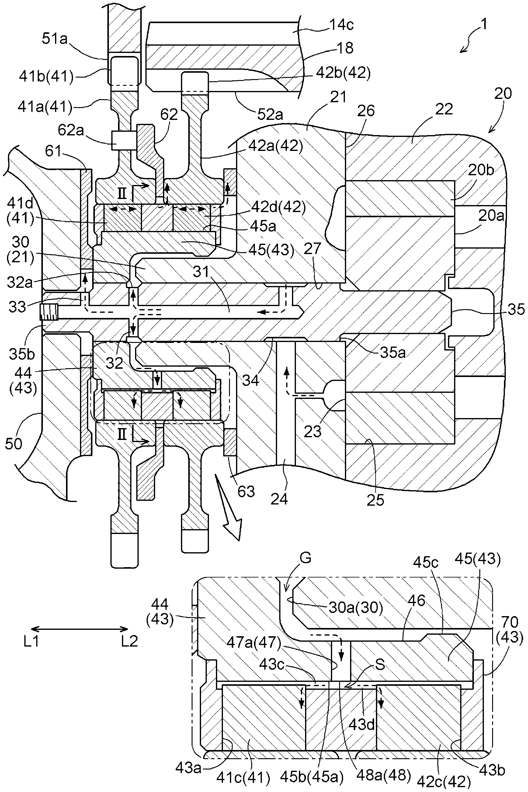
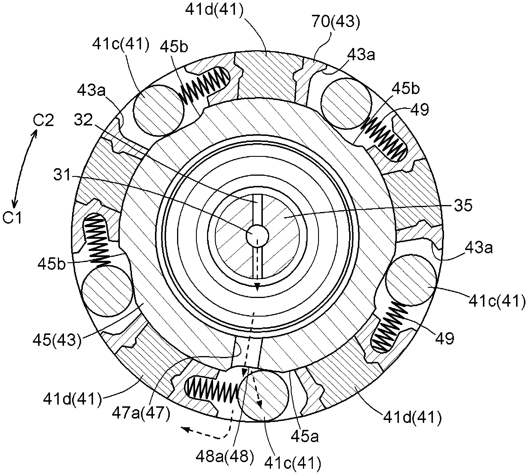
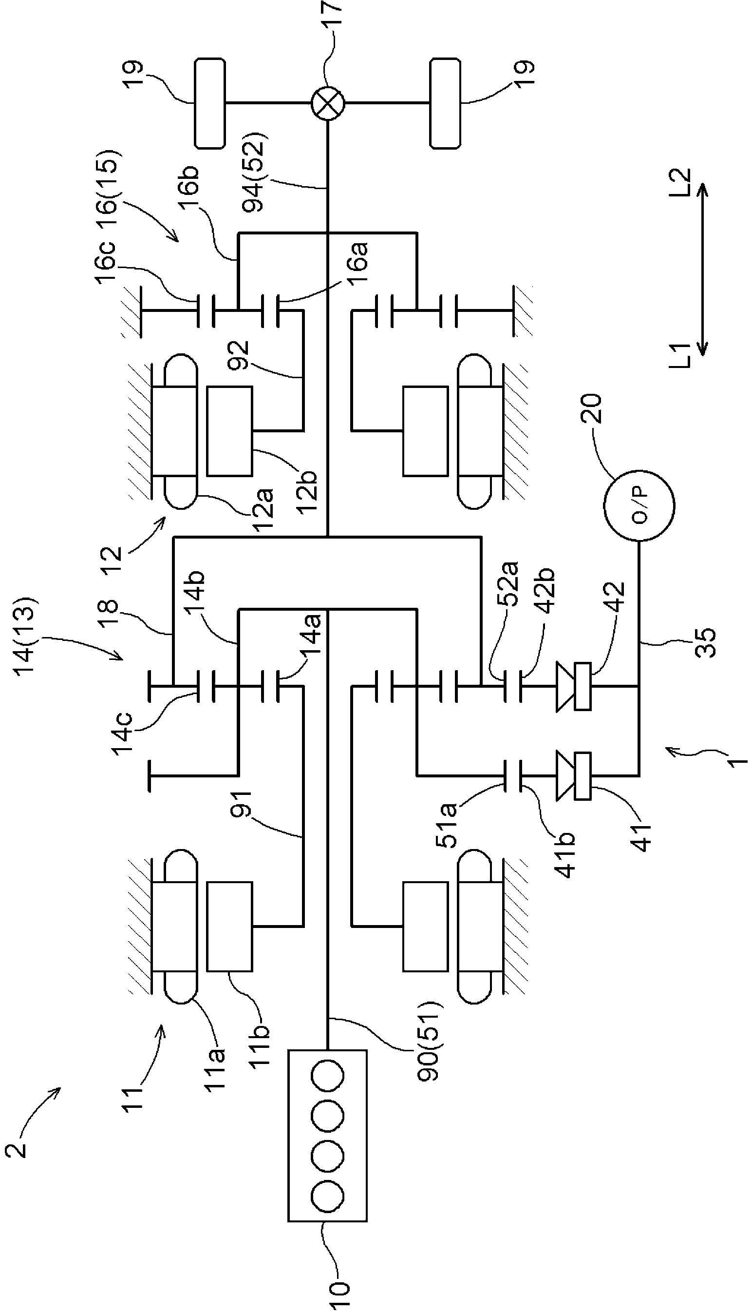
[0037] Embodiments of a hydraulic pressure generating device and a driving device according to the present invention will be described with reference to the drawings. Here, the case where the hydraulic pressure generating device of the present invention is used as a hydraulic pressure generating device for generating hydraulic pressure and the driving device of the present invention is a vehicle driving device having the hydraulic pressure generating device will be described as an example. Such as figure 1 As shown, the oil pressure generating device 1 of this embodiment has the following characteristics: the pump housings 21, 22 have the protrusions 30 radially supporting the pump drive shaft 35, and the two one-way clutches 41, 42 have respective The shared inner wheel 43 that the inner wheels of the inner wheels are integrated with each other. Also, the common inner wheel 43 has a main body portion 45 having a portion located radially outside of the protruding portion 30 a...


PUM


Abstract

A liquid pressure generating apparatus including a pump, and two one-way clutches arranged coaxially with the pump drive shaft in a line in the axial direction on the side of a first axial direction. The pump case includes a projecting portion projecting from the corresponding pump case. Inner races of the respective two one-way clutches are integrated with each other and form a common inner race. Outer races of the respective two one-way clutches are formed independently from each other and are driven respectively by pump driving members different from each other, and directions of restricted relative rotation with respect to the common inner race are identical to each other. The common inner race includes a coupling portion to be coupled to the pump driving shaft on the side of the first axial direction with respect to the projecting portion.

Description

technical field [0001] The invention relates to a hydraulic pressure generating device and a driving device with the hydraulic pressure generating device. The hydraulic pressure generating device has: a pump with a pump casing and a pump drive shaft; One side in the axial direction of the shaft first direction side is arranged coaxially with the pump drive shaft in the axial direction. Background technique [0002] Conventional examples of a hydraulic pressure generator as an example of the aforementioned hydraulic pressure generator include, for example, hydraulic pressure generators described in Patent Document 1 and Patent Document 2 below. Specifically, both Patent Document 1 and Patent Document 2 disclose a structure in which the relative rotation direction of the outer wheel relative to the inner wheel is restricted (hereinafter referred to as Configure the two one-way clutches in the same manner as each other for the "object direction"), and the inner wheels of the t...

Claims


Application Information

Patent Timeline
IPC IPC(8): F16H57/04B60K6/40B60K17/06B60L50/16
CPCF16H61/0028Y02T10/6239F16H2037/0866B60K6/445Y02T10/62
Inventor 野村晋一吉川博森笃豊田浩也渡边亮铃木晴久岩野彰
Owner AISIN AW CO LTD
Why Eureka
Try Eureka