Termination connection for superconductive cable

A superconducting cable and terminal connection technology, applied in the directions of superconducting devices, superconducting parts, superconducting elements, etc., can solve problems such as the performance degradation of superconducting cables 10, and prevent the generation of stress, peeling and damage. , the effect of maintaining integrity

Active Publication Date: 2013-03-27
FURUKAWA ELECTRIC CO LTD
View PDF7 Cites 8 Cited by
  • Summary
  • Abstract
  • Description
  • Claims
  • Application Information

AI Technical Summary

Problems solved by technology

Furthermore, the superconducting wire constituting the superconducting conductor layer 112 or the superconductin

Method used


Image

  • Termination connection for superconductive cable
  • Termination connection for superconductive cable
  • Termination connection for superconductive cable

Examples


Example

[0072] [first embodiment]

[0073] Hereinafter, a first embodiment of the present invention will be described in detail based on the drawings.

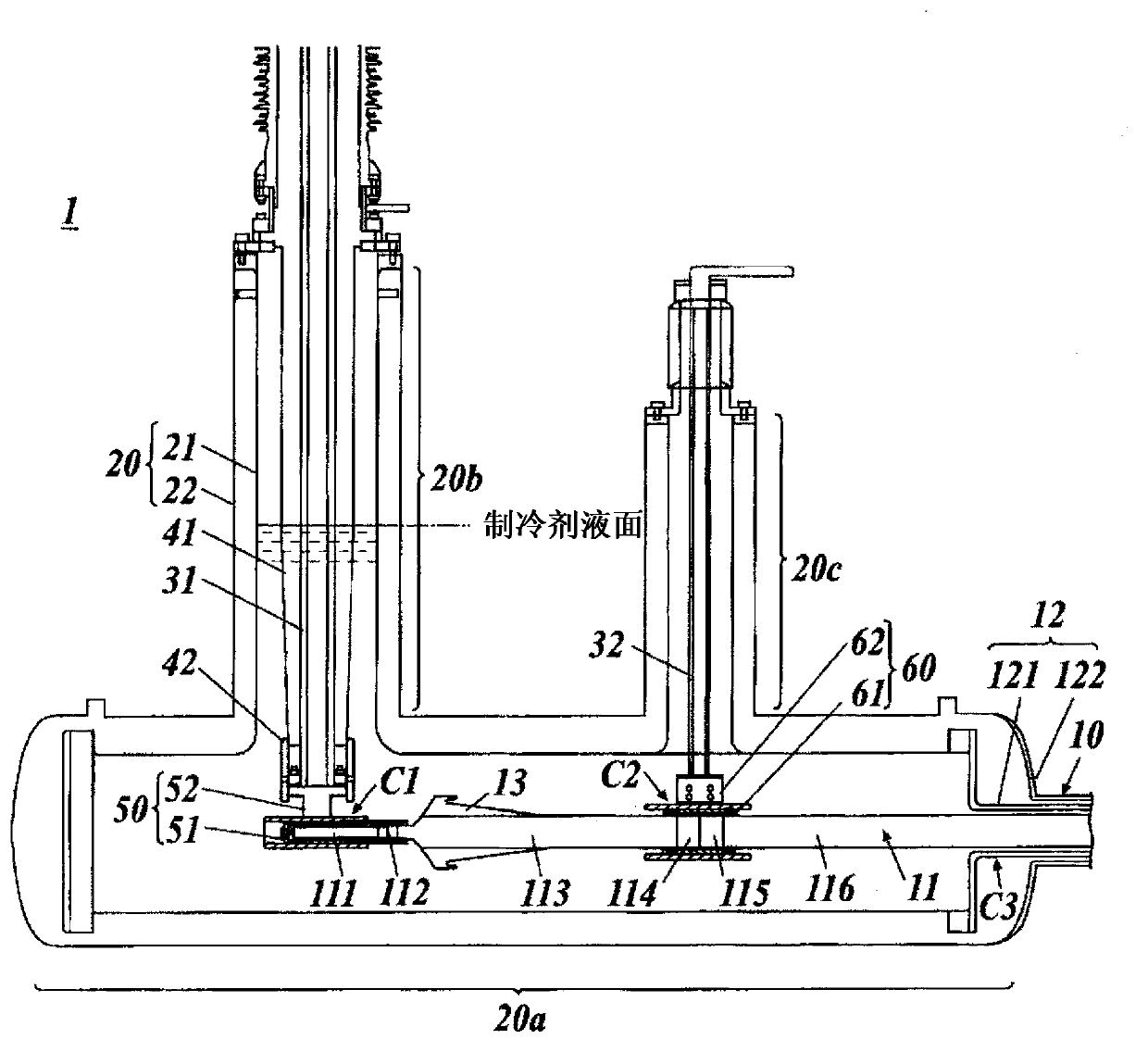
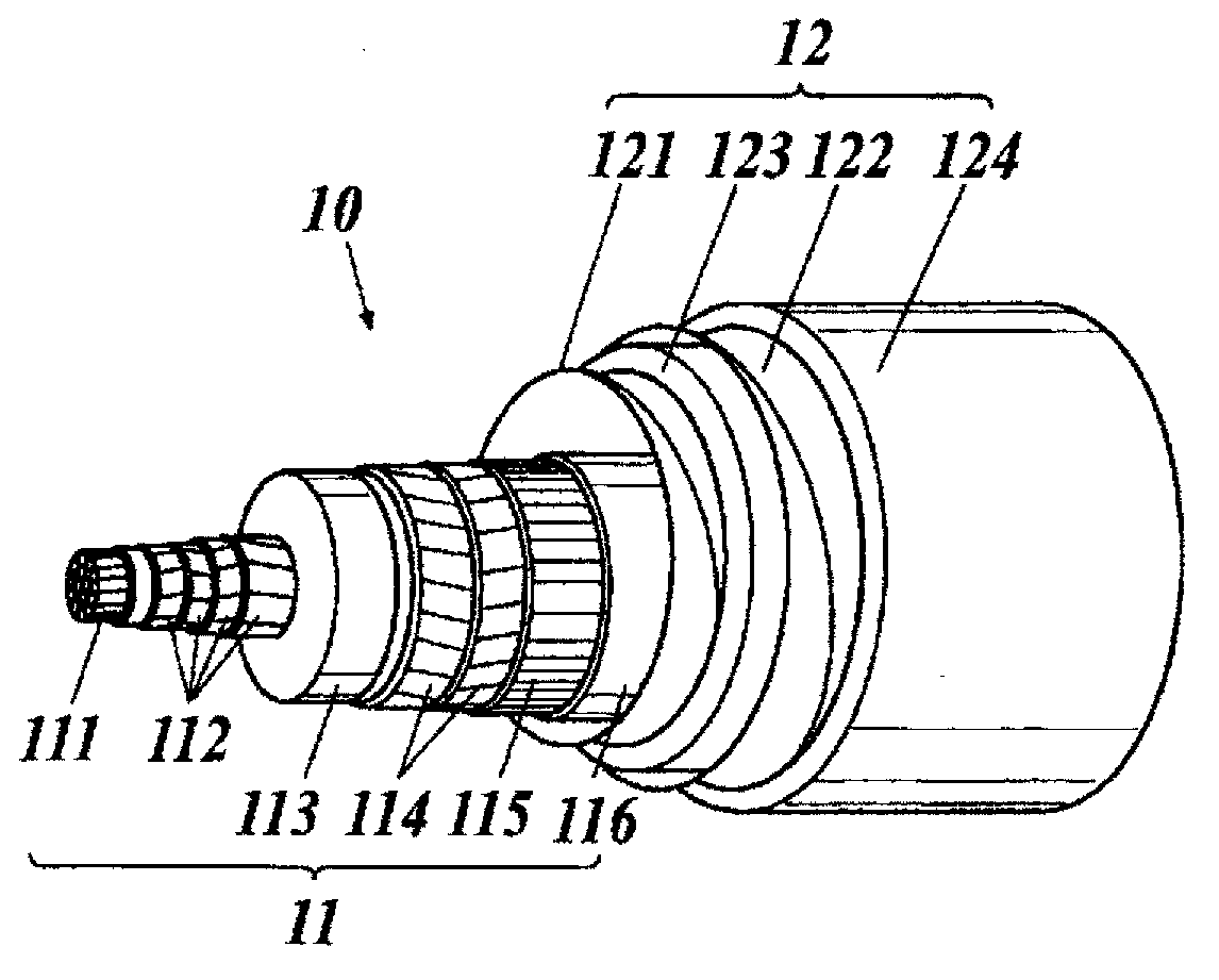
[0074] figure 1 It is a figure which shows the schematic structure of the terminal connection part of the superconducting cable of 1st Embodiment, figure 2 It is a figure which shows an example of the superconducting cable which should equip the terminal connection part.

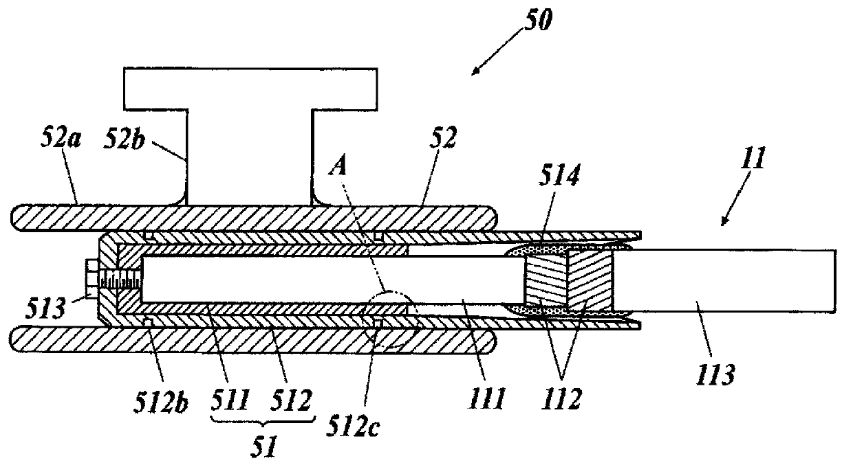
[0075] figure 2 The shown superconducting cable 10 is a single-core superconducting cable in which a cable core 11 of one core is accommodated in a heat insulating tube 12 . The cable core 11 is composed of a skeleton (forma) 111 , a superconducting conductor layer 112 , an electrical insulating layer 113 , a superconducting shielding layer 114 , a common conductive shielding layer 115 , and a protective layer 116 .

[0076] The skeleton 111 is a winding core for forming the cable core 11 , and is formed, for example, by twisting common conductive wires such as...


PUM


Abstract

A termination connection is configured by being provided with: a low-temperature container filled with a refrigerant; a current lead for a conductor, one end of the current lead being immersed in the refrigerant while the other end is pulled out to a normal temperature section; and a movable connection terminal for a conductor, the movable connection terminal electrically connecting the current lead for a conductor with the superconductive conductor layer of a superconductive cable. The superconductive conductor layer of a superconductive cable, of which the ends are stripped, is connected to the current lead for a conductor via the movable connection terminal for a conductor. The cable core of the superconductive cable can move in the lengthwise direction and rotate in the circumferential direction while keeping the superconductive conductor layer electrically connected to the current lead for a conductor. Moreover, the cable core is horizontally supported within the low-temperature container. As a consequence of the aforementioned configuration, the thermal expansion of the cable core under a heat cycle is absorbed, thereby being able to provide a simplified termination connection of which the size is reduced.

Description

technical field [0001] The present invention relates to a terminal connection part of a superconducting cable formed by accommodating a cable core having a skeleton and a superconducting conductor layer in a heat insulating tube. Background technique [0002] Conventionally, a superconducting cable using a superconducting wire that becomes superconducting at an extremely low temperature as a conductor is known. Superconducting cables are expected as power cables capable of transmitting large currents with low loss, and superconducting cables are being developed toward practical use. [0003] figure 2 An example of a superconducting cable is shown in . figure 2 The shown superconducting cable 10 is a single-core superconducting cable in which a single-core cable core 11 is accommodated in a heat insulating tube 12 . [0004] The cable core 11 is composed of a skeleton 111 , a superconducting conductor layer 112 , an electrical insulating layer 113 , a superconducting shiel...

Claims


Application Information

Patent Timeline
IPC IPC(8): H02G15/34H01B12/12H01B12/16H01L39/04H01R4/68
CPCH01L39/02Y02E40/648H01R4/68H02G15/34H01B12/16Y02E40/60
Inventor 八木正史三觜隆治野村朋哉向山晋一平田平雄米村德伟
Owner FURUKAWA ELECTRIC CO LTD
Why Eureka
Try Eureka