Eureka AIR delivers breakthrough ideas for toughest innovation challenges, trusted by R&D personnel around the world.

Combined vacuum devolatilization device

A devolatilization device and combined technology, applied in chemical instruments and methods, methods of chemically changing substances by using atmospheric pressure, chemical/physical processes, etc., can solve problems such as low pressure, poisoning the human body, polluting the environment, etc., and achieve Water saving, good devolatilization effect, wide application effect

Active Publication Date: 2013-04-03
苏州金纬片板膜智能装备有限公司
View PDF1 Cites 1 Cited by
  • Summary
  • Abstract
  • Description
  • Claims
  • Application Information

AI Technical Summary

Problems solved by technology

[0004] The entire devolatilization process has also experienced a process from simple to complex, from low-pressure low-efficiency to high-pressure high-efficiency. Initially, the devolatilization process is used in chemical production by using the medium and low negative pressure generated by the air inlet of the vortex air pump or high-pressure fan. The pressure is low and the effect is not good. Later, high-pressure equipment such as water jet vacuum pumps or Roots blowers are used to assist filter pipelines in chemical production. However, due to the complexity of chemical production, corrosive solvents or monomers often damage equipment, and Poison the human body, pollute the environment, and cannot be recycled

Method used


Image

  • Combined vacuum devolatilization device

Examples


Embodiment Construction

[0016] In order to make the object, technical solution and advantages of the present invention clearer, the present invention will be further described in detail below in conjunction with the accompanying drawings.

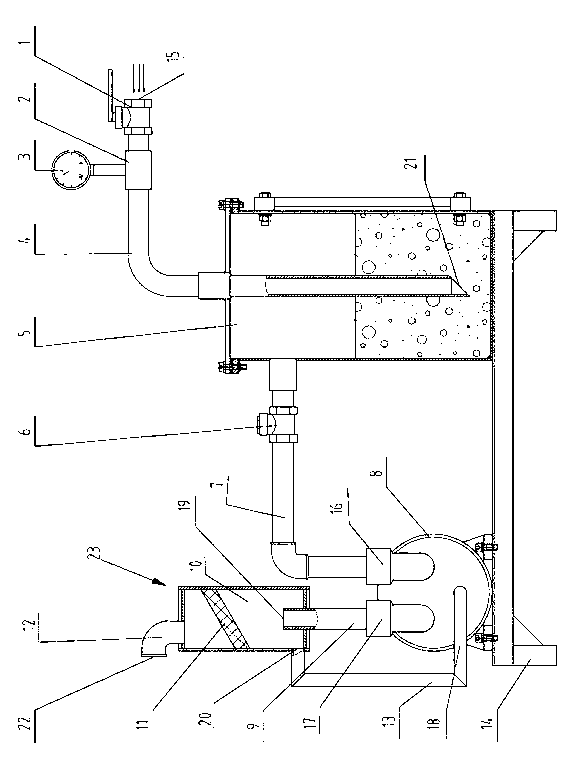
[0017] Such as figure 1 The combined vacuum devolatilization device shown has a base 14 at the bottom, and a water ring vacuum pump 8 and a vacuum cylinder 5 are respectively arranged above the base 14 on one left and one right.

[0018] The three holes on the water ring vacuum pump 8 are vacuum inlet 16, vacuum outlet 17, and vacuum water inlet 18 respectively. Water enters the water ring vacuum pump 8 through the vacuum water inlet 18 and acts as a seal when the water ring vacuum pump 8 is working. Function, when the water ring vacuum pump 8 works, it will generate a negative pressure at the vacuum inlet 16, suck in air, and discharge the mixture formed by the air entering the vacuum inlet 16 and the water entering through the vacuum water inlet 18 through the v...


PUM


Abstract

The invention relates to a combined vacuum devolatilization device. The device comprises a base, a vacuum cylinder, a water ring vacuum pump and an exhaust tube, wherein a cavity is arranged inside the vacuum cylinder; filtering water is stored in the lower part of the cavity; one end part of the exhaust tube is provided with a vacuumizing port, and the other end part of the exhaust tube is provided with an outlet of the exhaust tube; the outlet of the exhaust tube is inserted into the filtering water in the lower part of the cavity; the water ring vacuum pump is provided with a vacuum inlet, a vacuum outlet and a vacuum water inlet, which are communicated with the inside of the water ring vacuum pump; the vacuum inlet is communicated with the upper part of the cavity of the vacuum cylinder; a gas-water separation unit is arranged between the vacuum outlet and the vacuum water inlet and is internally provided with a separation cavity; a water return opening and a venting tube communicated with the separation cavity are arranged on the gas-water separation unit; the vacuum outlet is communicated with the separation cavity; and the water return opening is communicated with the vacuum water inlet. Polluted air generated in an industrial production process can be efficiently treated by the combined vacuum devolatilization device. Furthermore, the combined vacuum devolatilization device has the characteristics of no pollution, no poison, energy conservation, environment protection, and wide application.

Description

[0001] technical field [0002] The invention relates to a combined vacuum devolatilization device. Background technique [0003] Devolatilization is a process that is driven by thermodynamics and assisted by a vacuum system to remove the solvent from the polymer and extract the monomer. It is a very commonly used process in modern industrial production. [0004] The entire devolatilization process has also experienced a process from simple to complex, from low-pressure low-efficiency to high-pressure high-efficiency. Initially, the devolatilization process is used in chemical production by using the medium and low negative pressure generated by the air inlet of the vortex air pump or high-pressure fan. The pressure is low and the effect is not good. Later, high-pressure equipment such as water jet vacuum pumps or Roots blowers are used to assist filter pipelines in chemical production. However, due to the complexity of chemical production, corrosive solvents or monomers oft...

Claims


Application Information

Patent Timeline
Patent Type & Authority Applications(China)
IPC IPC(8): B01J3/00
Inventor 何海潮吕山
Owner 苏州金纬片板膜智能装备有限公司
Why Eureka
Eureka Blog
Learn More