Eureka AIR delivers breakthrough ideas for toughest innovation challenges, trusted by R&D personnel around the world.

Exhaust anti-spilling device

An exhaust machine and screw technology, applied in the field of chemical equipment, can solve the problems of reducing volatile matter discharge, affecting product quality, and product inclusion of black particles, etc., to achieve the effect of preventing backflow, increasing the exposed area of ​​materials, and strengthening the sealing effect

Pending Publication Date: 2018-07-06
PETROCHINA CO LTD
View PDF7 Cites 0 Cited by
  • Summary
  • Abstract
  • Description
  • Claims
  • Application Information

AI Technical Summary

Problems solved by technology

[0002] During the production process of chlorosulfonated polyethylene, the wet glue enters the extruder, and under the action of the barrel, screw and heating elements, the volatiles such as solvent and water are separated and discharged through the exhaust port on the barrel, volatilized During the discharge process, the chlorosulfonated polyethylene rubber in the barrel also overflows, and the rubber gradually blocks the exhaust port, reducing the discharge of volatile matter and affecting product quality; moreover, the overflowing rubber is heated and carbonized by the barrel, and the exhaust gas is cleaned up. During the exhaust process, it is easy to enter the barrel through the exhaust port, making the product mixed with black particles and affecting product quality

Method used


Image

  • Exhaust anti-spilling device
  • Exhaust anti-spilling device
  • Exhaust anti-spilling device

Examples


Embodiment Construction

[0029] The present invention is further described below in conjunction with accompanying drawing and embodiment, and the embodiment that enumerates is the example that practical operation is verified in the large-scale trial production, therefore is easy to be mastered by those skilled in the art. If some changes are made on the basis of the present invention, the essence does not exceed the scope of the present invention, and the examples described are only to illustrate the present invention, and do not limit the present invention.

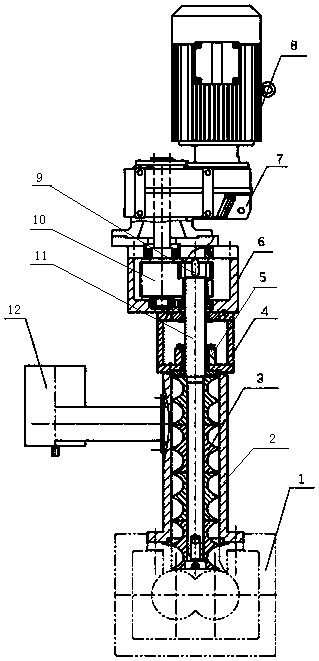
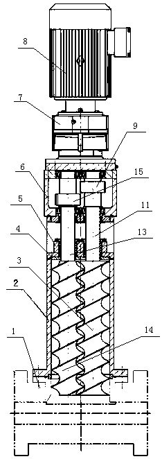
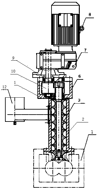
[0030] refer to Figure 1-2 , Embodiment 1, the present embodiment is an exhaust anti-overflow device, which includes an exhaust machine, a distribution box 6, a speed reducer 7 and a motor 8, and the lower end of the exhaust machine is fixedly connected with the open barrel 1 at the upper end of the main machine , and communicate with the main machine through the opening barrel 1 at the upper end of the main machine, the upper end of the exhaus...


PUM


Abstract

The invention discloses an exhaust anti-spilling device. The exhaust anti-spilling device is characterized by comprising an exhaust machine, the lower end of the exhaust machine is fixedly connected with an opening machine cylinder at the upper end of a main machine, the upper end of the exhaust machine is fixedly connected with a distribution box in a sealed manner, an input shaft of the distribution box is fixedly connected with a power output shaft of a speed reducer, an output shaft of the distribution box is fixedly connected with a power input shaft of the exhaust machine, and a power shaft of an electric motor is fixedly connected with the input shaft of the distribution box. According to the work process, the electric motor speed reducer transmits power to the input shaft of the distribution box, a driving gear transmits power to a first shaft and a second shaft through a first driven gear and a second driven gear, a first screw rod and a second screw rod are driven to rotate in the same direction, the first screw rod and the second screw rod continuously push and press rubber flowing out of the opening machine cylinder to the interior of the main machine, the rubber entersthe position between tooth grooves of the first screw rod and the second screw rod and the inner wall of the machine cylinder and an exhaust channel formed by the first screw rod and the second screwrod, and then the rubber passes through the machine cylinder of the exhaust machine upwards and enters an exhaust pipe to be discharged out.

Description

technical field [0001] The invention relates to chemical equipment, in particular to the discharge of volatile matter from a chlorosulfonated polyethylene rubber extruder, and is an exhaust and overflow prevention device for the exhaust and overflow prevention device of a chlorosulfonated polyethylene rubber extruder. Background technique [0002] During the production process of chlorosulfonated polyethylene, the wet glue enters the extruder, and under the action of the barrel, screw and heating elements, the volatiles such as solvent and water are separated and discharged through the exhaust port on the barrel, volatilized During the discharge process, the chlorosulfonated polyethylene rubber in the barrel also overflows, and the rubber gradually blocks the exhaust port, reducing the discharge of volatile matter and affecting product quality; moreover, the overflowing rubber is heated and carbonized by the barrel, and the exhaust gas is cleaned up. During the discharge pro...

Claims


Application Information

Patent Timeline
Patent Type & Authority Applications(China)
IPC IPC(8): B29C47/76B29C48/76
CPCB29C48/761B29C48/763B29C48/766
Inventor 毕学文蒋蔺姜城孙建刚王原钦奚昊钱同云芦伟叶遥
Owner PETROCHINA CO LTD
Why Eureka
Eureka Blog
Learn More