
Forming device of rapid heating and cooling separation type continuous carbon fiber thermoplastic U-shaped part and process

A technology of cooling separation and rapid heating, applied in the field of molding devices, can solve the problems of poor product surface quality, high equipment requirements, and high energy consumption, and achieve the effects of facilitating rapid heating, increasing heat exchange area, and improving heat exchange efficiency

Pending Publication Date: 2020-12-15
ZHENGZHOU UNIV +1
View PDF0 Cites 6 Cited by
  • Summary
  • Abstract
  • Description
  • Claims
  • Application Information

AI Technical Summary

Problems solved by technology

[0003] The existing molding methods of continuous carbon fiber reinforced thermoplastic parts mainly include cold mold pressing and hot mold pressing. The advantage of cold mold pressing is that the prepreg heating and mold pressing after layering can be carried out at different stations at the same time. The production efficiency is high, but the disadvantage is that the prepreg after heating and softening needs to be kept warm during the station transfer process, which requires high equipment. If the heat preservation effect is not good, the surface of the prepreg will be partially hardened, resulting in poor surface quality of the product. The advantages of hot mold pressing are that the prepreg is heated and softened in the mold, hot-pressed, the product is heated evenly, the interlayer is well bonded, and the surface quality is guaranteed. The disadvantage is that the mold needs to be prepreg when molding. Cooling after heating, high energy consumption and low production efficiency

Method used


Image

  • Forming device of rapid heating and cooling separation type continuous carbon fiber thermoplastic U-shaped part and process
  • Forming device of rapid heating and cooling separation type continuous carbon fiber thermoplastic U-shaped part and process
  • Forming device of rapid heating and cooling separation type continuous carbon fiber thermoplastic U-shaped part and process

Examples


Embodiment Construction

[0037] The technical solutions of the present invention will be described in further detail below through specific embodiments.

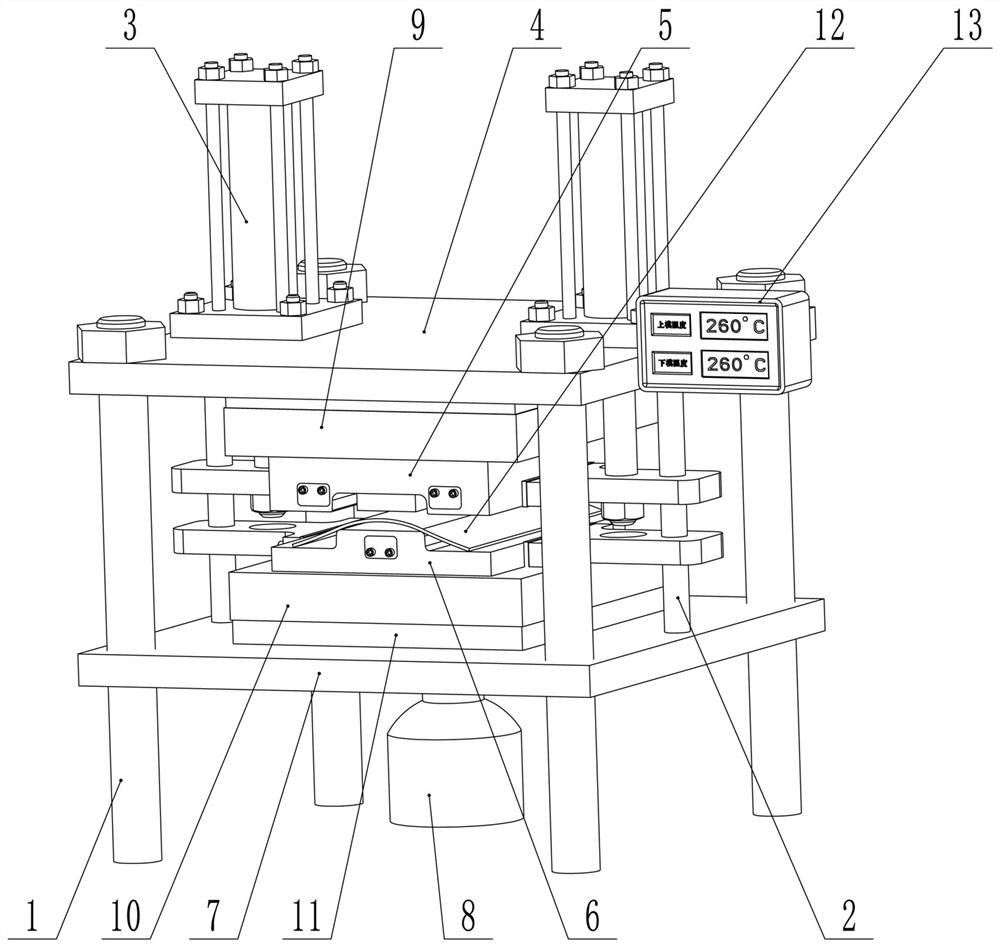
[0038] Such as Figure 1 to Figure 4As shown, a rapid heating and cooling separation type continuous carbon fiber thermoplastic U-shaped part forming device includes an upper drive mechanism, a lower drive mechanism, four Green columns 1, two vertical slide bars 2 and sequentially arranged from top to bottom The upper base, the upper mold 5, the lower mold 6 and the lower base corresponding to the upper mold 5, the bottom of the upper base is provided with an upper heating plate 9, and the top of the lower base is provided with a lower heating plate 10, Both the upper mold 5 and the lower mold 6 are embedded with a cooling mechanism; the two ends of the upper mold 5 and the lower mold 6 are respectively sleeved on the two vertical slide bars 2 , the upper drive mechanism drives the upper mold 5 up and down, the lower mold 6 is provided with a minim...


PUM


Abstract

The invention provides a forming device of rapid heating and cooling separation type continuous carbon fiber thermoplastic U-shaped part. The forming device comprises an upper driving mechanism, a lower driving mechanism, a vertical guide mechanism, an upper base, an upper mold, a lower mold and a lower base, wherein the upper base, the upper mold, the lower mold and the lower base are sequentially arranged from top to bottom; a lower heating plate is arranged at the top of the lower base, a cooling mechanism is embedded in each of the upper mold and the lower mold, the upper driving mechanismdrives the upper mold to ascend and descend along the vertical guide mechanism, the lower mold is installed on the vertical guide mechanism and can ascend and descend along the vertical guide mechanism, and the vertical guide mechanism is provided with a lowest limiting mechanism corresponding to the lower mold; and the lower driving mechanism drives the lower base to ascend and descend along thevertical guide mechanism. The invention further provides a forming process of the continuous carbon fiber thermoplastic U-shaped part. The forming device of the rapid heating and cooling separation type continuous carbon fiber thermoplastic U-shaped part and the process have the advantages of being scientific in design, high in production efficiency, low in energy consumption, good in product quality, economical and applicable.

Description

technical field [0001] The invention relates to a forming device and process, in particular to a rapid heating and cooling separation type continuous carbon fiber thermoplastic U-shaped part forming device and process method. Background technique [0002] Compared with continuous carbon fiber-reinforced thermosetting composite products, continuous carbon fiber-reinforced thermoplastic composite products have good toughness, and their molding is a physical process with high production efficiency. They have been widely used in various fields in recent years. [0003] The existing molding methods of continuous carbon fiber reinforced thermoplastic parts mainly include cold mold pressing and hot mold pressing. The advantage of cold mold pressing is that the prepreg heating and mold molding after laying up layers can be carried out at different stations at the same time. The production efficiency is high, but the disadvantage is that the prepreg after heating and softening needs ...

Claims


Application Information

Patent Timeline
IPC IPC(8): B29C70/42B29C33/02B29C33/04B29C33/24B29C33/30B29K105/10
CPCB29C33/02B29C33/04B29C33/24B29C33/303B29C70/42B29K2105/0881
Inventor 黄明韦韡张娜郭传科石宪章刘春太陆川军朱华平
Owner ZHENGZHOU UNIV
Learn More