
Stirring tank

A technology of stirring tank and stirring shaft, which is applied in the field of stirring tank, can solve the problems of reducing catalyst efficiency and effect, sticking to the wall, stirring dead zone, etc., to shorten heating or cooling time, improve efficiency and effect, and improve heat exchange effect Effect

Active Publication Date: 2013-04-03
CHINA PETROLEUM & CHEM CORP +1
View PDF5 Cites 8 Cited by
  • Summary
  • Abstract
  • Description
  • Claims
  • Application Information

AI Technical Summary

Problems solved by technology

At this stage, the various stirred tanks in the industry mainly use the stirring shaft of the impeller to be stirred, and there are still stirring dead zones and wall sticking phenomena in the process of gelling, which will reduce the efficiency and effect of catalyst production.

Method used


Image

  • Stirring tank
  • Stirring tank
  • Stirring tank

Examples


Embodiment Construction

[0030] Specific embodiments of the present invention will be described in detail below in conjunction with the accompanying drawings. It should be understood that the specific embodiments described here are only used to illustrate and explain the present invention, and are not intended to limit the present invention.

[0031] In the present invention, in the absence of a contrary statement, the orientation words used such as "upper and lower" are usually defined under the normal use of the stirred tank provided by the present invention, specifically, as figure 1 direction shown.

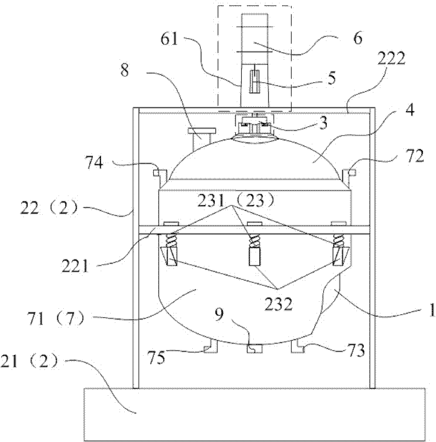
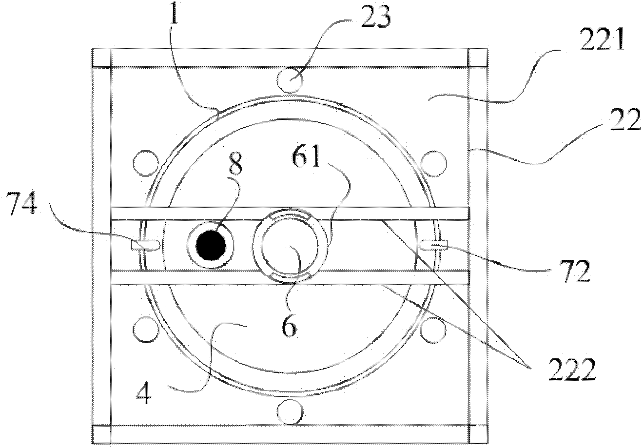
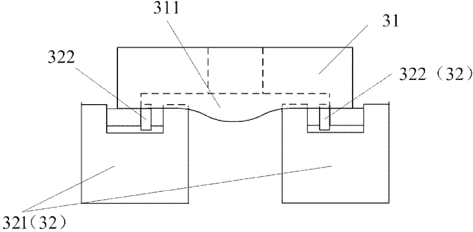
[0032] according to figure 1 As shown, the present invention provides a stirred tank, which includes a tank body 1, and the stirred tank also includes an elastic support 2 and a vibration device 3, the tank body 1 is fixed on the elastic support 2, and the vibration device 3 is located at the tank body 1, and drive the kettle body 1 to vibrate on the elastic support 2, and the kettle body 1 is prov...


PUM


Abstract

The invention discloses a stirring tank which comprises a tank body, and further comprises an elastic support and a vibrating device, wherein the tank body is fixed on the elastic support, the vibrating device is located at an upper end of the tank body and vibrates on the elastic support, and the tank body is provided with a heat exchanging device which can adjust temperature in the tank body through exchanging heat with the tank body. The upper end of the tank body of the stirring tank is provided with the vibrating device and the tank body is fixed on the elastic support, so that the tank body can vibrate. While reacted, substances in the stirring tank can be stirred and vibrated as well, and therefore, the stirring tank provided by invention can effectively prevent phenomena of stirring dead zones and wall sticking during the reaction, so the reacting substances can be fully stirred. In addition, the heat exchanging device is arranged on the tank body, and can cooperate with the vibrating device to realize effective regulation of the temperature in the tank body, thereby effectively improving reaction efficiency and effect.

Description

technical field [0001] The invention relates to a reaction device, in particular to a stirred tank. Background technique [0002] Stirred tanks are widely used in the chemical industry. For example, in the production of catalysts, stirred tanks are one of the core equipment. Because catalysts such as cracking catalysts are inorganic powdery granular products, and are mainly used in refining catalytic cracking units. The product has a large amount of use and high technical content, and has strict requirements on various technical indicators such as physical chemistry. Therefore, the production process of the catalyst is complicated, and the performance requirements for the production equipment are relatively high. In the process of using stirred tanks to produce catalysts, gelation reactions are often involved. The basic materials are liquid phases, and the added materials are solid phases. Therefore, to ensure that various gel-forming materials are fully and evenly mixed, ...

Claims


Application Information

Patent Timeline
Patent Type & Authority Applications(China)
IPC IPC(8): B01J19/18B01F13/10
Inventor 周治周岩张志民田辉平刘宇键朱玉霞许昀赵留周杨凌陶金张志良罗斌尹哲赵伟
Owner CHINA PETROLEUM & CHEM CORP
Learn More