Multilevel-positioning scraping plate of rotary cutter

A knife row and rotary knife technology is applied to multi-stage positioning scraping of rotary knives. It can solve the problems that affect the manufacturing cost of product headers and the manufacturing cycle of product headers, and achieve the effect of being convenient for large-scale use, low manufacturing cost, and easy to take out and operate.

Active Publication Date: 2013-04-03
SHANGHAI BOILER WORKS
View PDF14 Cites 14 Cited by
  • Summary
  • Abstract
  • Description
  • Claims
  • Application Information

AI Technical Summary

Problems solved by technology

Using a fixed reverse scraper to process grooves on the inner walls of pipe holes with different diameters requires frequent replacement of the inclined hole row body 4 and adjustment of the installation position of the scraper 2, wh

Method used


Image

  • Multilevel-positioning scraping plate of rotary cutter
  • Multilevel-positioning scraping plate of rotary cutter
  • Multilevel-positioning scraping plate of rotary cutter

Examples


Embodiment 1

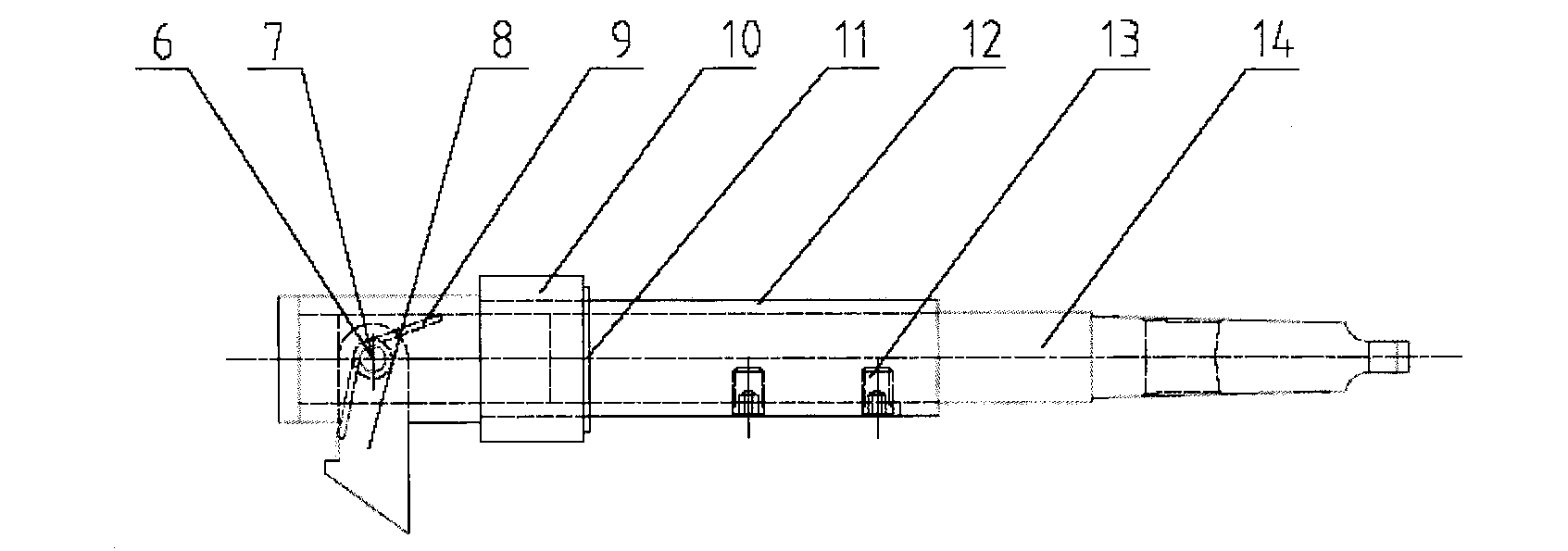
[0048] Such as figure 2 As shown, it is a side view of the first rotary knife multi-stage positioning scraper. The rotary knife multi-stage positioning scraper includes a pin shaft 6, a cotter pin 7, a flip scraper 8, a torsion spring 9, a positioning ring 10, and a retaining ring 11. Sliding sleeve 12, hexagon socket set screw 13 and first knife row body 14.

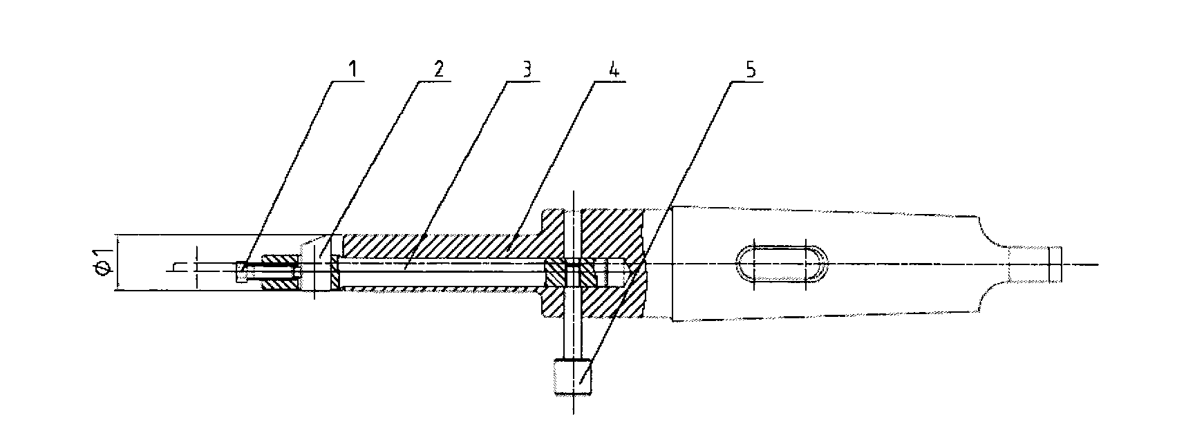
[0049] Such as image 3 As shown, the first knife row body 14 has a knife-mounting groove, and a turning scraper 8 is arranged in the knife-mounting groove, and the turning scraper 8 is fixed in the knife-mounting groove of the first knife-row body 14 through the pin shaft 6 and the cotter pin 7, and the flipping A torsion spring 9 is embedded in the center hole of the scraper 8, the lower end of the torsion spring 9 is buckled on the turning scraper 8, and the upper end of the torsion spring 9 is buckled on the first knife row body 14, and the first knife row body 14 is provided with a slip The sleeve 12, through th...

Embodiment 2

[0058] Such as Figure 14 As shown, it is a side view of the second rotary knife multi-stage positioning scraper. The rotary knife multi-stage positioning scraper includes a retaining ring 10, a positioning ring 15, a pin shaft 6, a cotter pin 7, a flat scraper 16, and a torsion spring. 9. The sliding bushing 17 and the second blade row body 18 .

[0059] Such as Figure 15 As shown, the second knife row body 18 has a knife-mounting groove, and a flat scraper 16 is arranged in the knife-mounting groove. A torsion spring 9 is embedded in the central hole of the scraper 16, the lower end of the torsion spring 9 is buckled on the flat scraper 16, and the upper end of the torsion spring 9 is buckled on the second knife row body 18, and the second knife row body 18 is provided with a sliding The bushing 17 can press the flat scraper 16 into the knife slot through the sliding of the sliding bushing 17 , and a positioning ring 15 is provided on the outside of the second knife row b...


PUM

PropertyMeasurementUnit
Angleaaaaaaaaaa

Abstract

The invention provides a multilevel-positioning scraping plate of a rotary cutter. The multilevel-positioning scraping plate is characterized by comprising a cutter plate body, wherein the cutter plate body is provided with a cutter loading slot; the cutter loading slot is internally provided with a scraper; the scraper is fixed in the cutter loading slot of the cutter plate body by virtue of a pin shaft and a split pin; a torsional spring is embedded in the center hole of the scraper; the lower end of the torsional spring is buckled on the scraper; the upper end of the torsional spring is buckled on the cutter plate body; and the cutter plate body is provided with a locating device and a slippage device capable of pressing the scraper into the cutter loading slot. The device provided by the invention can selectively assemble corresponding overturning scrapers and locating rings by aiming at pipe orifice with different orifice diameters and different reverse groove sizes, is high in universality and convenient in production department storage, and simultaneously has the advantages of simple overall structure, convenience in use and operation, low manufacturing cost and the like.

Description

technical field [0001] The invention provides a rotary knife multi-stage positioning scraper. Background technique [0002] In the prior art, the groove of the inner wall of the boiler header pipe joint is usually processed by using a fixed reverse scraper. Such as figure 1 As shown, it is a schematic diagram of the structure of the fixed reverse scraper. The fixed reverse scraper consists of five parts: screw 1, scraper 2, mandrel cutter bar 3, inclined hole row body 4 and pendulum 5. Its central shaft cutter bar 3 is installed in the inclined hole row body 4, and the offset distance h between the two center lines. Now take the processing of the groove on the inner wall of the boiler header pipe joint as an example, the mandrel cutter bar 3 is turned over 180 degrees in the inclined hole row body 4, that is, the diameter of the groove processing: Φ1+2h. Using a fixed reverse scraper to process grooves on the inner walls of pipe holes with different diameters requires fre...

Claims


Application Information

Patent Timeline
IPC IPC(8): B23D79/04
Inventor 陈力顾卫红钱月清印国忠丁海华
Owner SHANGHAI BOILER WORKS
Why Eureka
Try Eureka