

Thermal Transfer Receptive Sheet
A thermal transfer, sheet technology, used in printing, printing devices, copying/marking methods, etc., can solve the problems of complex manufacturing process, increased production cost, low productivity, etc., to achieve low bleeding, high sensitivity, The effect of excellent blocking resistance
- Summary
- Abstract
- Description
- Claims
- Application Information
AI Technical Summary
Problems solved by technology
Method used
Image

Examples
preparation example Construction
[0022] 2.1 Preparation of AS resin
[0023] 2.2 Synthesis of acrylic resin
[0024] 2.3 Preparation of mixed solution
[0025] 2.4 Coating and drying of mixed solution
[0026] [1. Composition of thermal transfer receiving sheet]
[0027] [1.1 Overall structure]
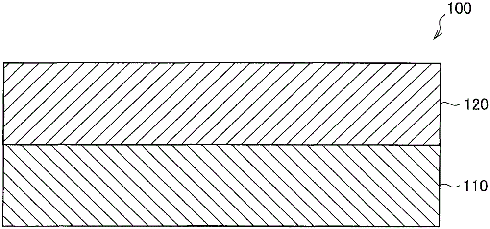
[0028] First, refer to figure 1 The general structure of the thermal transfer-receiving sheet according to the preferred embodiment of the present invention is described. figure 1 It is a schematic sectional view which shows the structure of the thermal transfer receiving sheet which concerns on a preferable embodiment of this invention.
[0029] Such as figure 1 As shown, the thermal transfer-receiving sheet 100 according to the present embodiment includes a base sheet 110 and a dye-receiving layer 120 formed on the base sheet 110 .
[0030] In general, the dye-receiving layer is formed using a polymer resin as a main component. In order to improve heat resistance, a curing agent such as polyisocyanate may b...
Embodiment 1
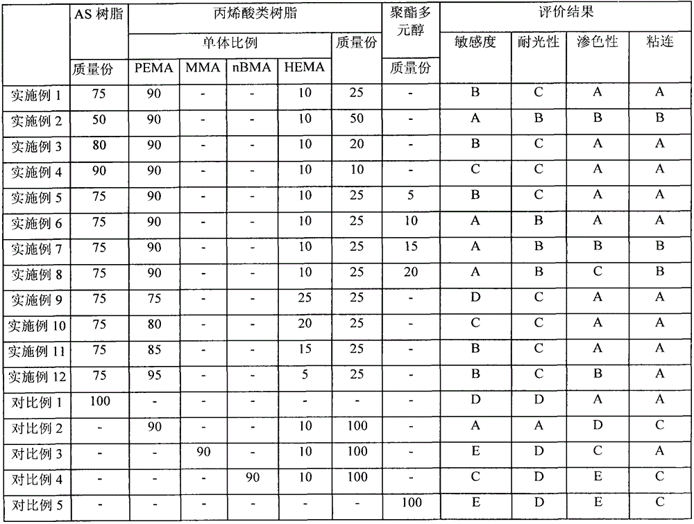
[0079] Based on the ratios listed in Table 1 below, AS-61 (a copolymer of styrene monomer and acrylonitrile monomer in a mixing ratio of 24:76) commercially available from NipponSteel Chemical Co., Ltd. was used as the AS resin, and PEMA / HEMA copolymer as acrylic resin. Then, mix AS resin and acrylic resin. Subsequently, the mixture was diluted with a mixed solvent of 2-butanone and toluene (mixing ratio 1:1) until the solid content of the mixture was 20% by mass, and then the mixed solution for forming the dye-receiving layer thus obtained was mixed with After the mixed solution was dried, it was coated on a 150 μm synthetic paper ("YUPOFPG-150" commercially available from OjiYuka) in an amount so as to have a thickness of 3 μm, and dried at 120° C. for 1 minute to remove the solvent, thereby preparing the paper of Example 1. Thermal transfer receiving sheet.
Embodiment 2 to 6 and comparative example 1 to 5
[0081] The thermal transfer-receiving sheets of Examples 2 to 12 and Comparative Examples 1 to 5 were produced in the same manner as described in Example 1, except for the content of AS resin, content of acrylic resin, content of PEMA and HEMA. The mixing ratio, the kind of the monomer of the acrylic resin and the content of the polyester polyol were varied as listed in Table 1.
[0082] [Printing method using thermal transfer receiving sheet]
[0083] Using a thermal transfer printer (UP-DR200 printer commercially available from Sony Corporation) and an ink ribbon containing yellow (Y), magenta (M) and cyan (C) dyes and having a laminated film (L) formed therein ( UPC-204 (commercially available from Sony Corporation) was printed on the thermal transfer-receiving sheets of Examples 1 to 12 and Comparative Examples 1 to 6 manufactured as described above.
[0084] [Evaluation method of thermal transfer receiving sheet]
[0085] After printing, each thermal transfer-receiving ...
PUM
| Property | Measurement | Unit |
|---|---|---|
| thickness | aaaaa | aaaaa |
Abstract
Description
Claims
Application Information