Linear moving device

A technology of linear movement and screw drive, which is applied in the direction of transportation and packaging, conveyors, mechanical conveyors, etc. It can solve problems such as non-parallel linear guide rails, deformation or twisting of the screw rod, and jamming of the screw rod and the screw nut. Achieve the effect of ensuring linear transmission accuracy, ensuring transmission stability, and avoiding deviation

Active Publication Date: 2013-04-03
NINGBO YUNSHENG INTELLIGENT TECHNOLOGY CO LTD +1
View PDF5 Cites 18 Cited by
  • Summary
  • Abstract
  • Description
  • Claims
  • Application Information

AI Technical Summary

Problems solved by technology

[0003] In the process of linear transmission of products, it is better to keep the screw rod parallel to the linear guide rail, but due to the limitation of machining accuracy and installation process, there must be a certain degree of non-parallel between the screw rod and the linear guide rail.
[0004] The stage is fixed with the slider, and the stage is fixed with the screw nut. During the linear transmission of the product, the stage must follow the slider to move linearly along the linear guide rail, and the stage must follow the screw nut. Move linearly along the screw; and the linear guide is not parallel to the screw; since the stiffness of the linear guide and the stage are greater than the stiffness of the screw, this will cause the screw to deform or twist under the traction of the screw nut, affecting The linear transmission accuracy of the linear moving device, when the deformation of the screw rod is serious, the screw rod and the screw nut will be stuck, and the linear moving device cannot work normally

Method used


Image

  • Linear moving device
  • Linear moving device
  • Linear moving device

Examples


Embodiment

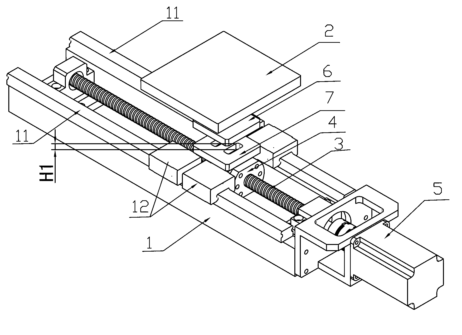
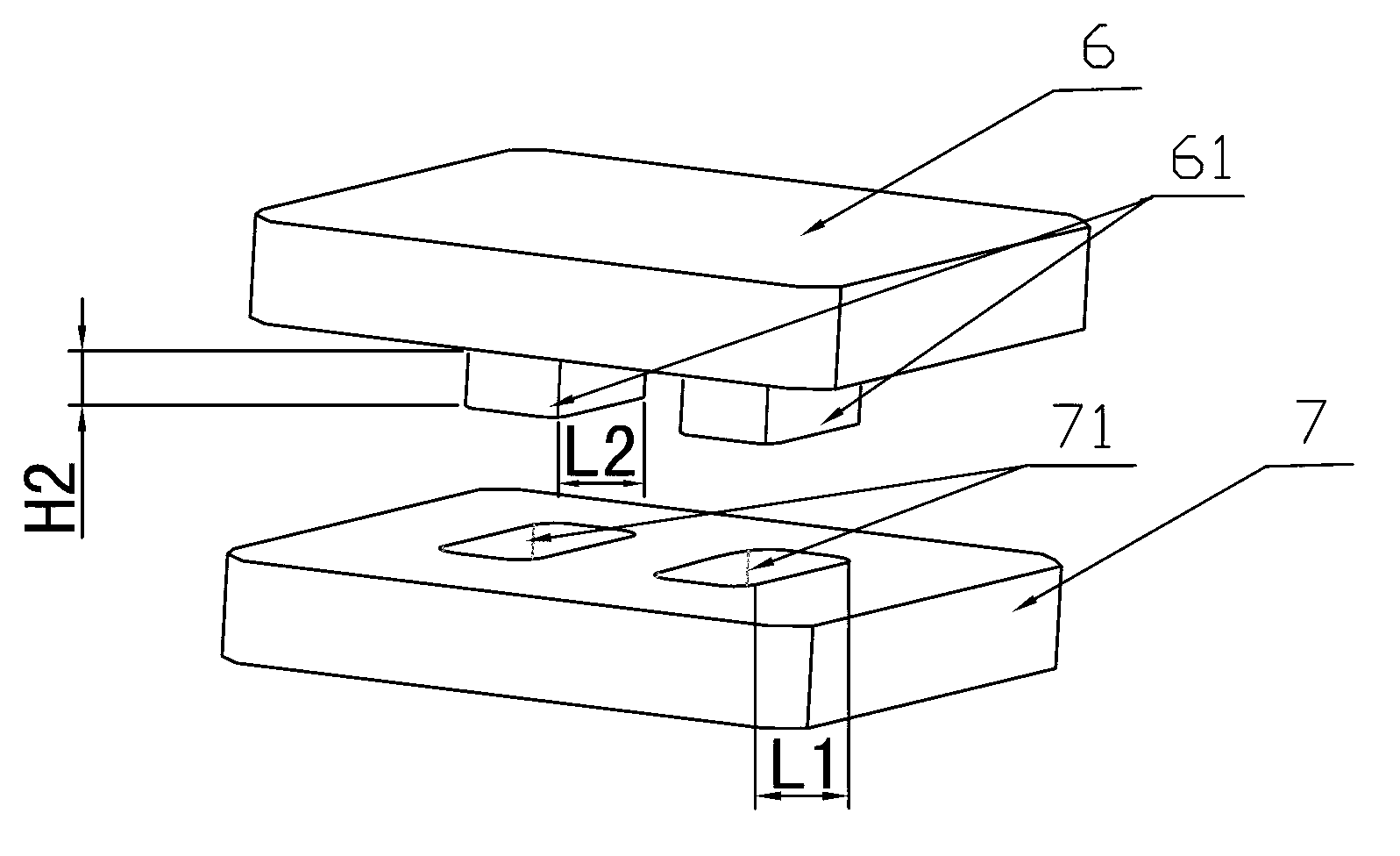
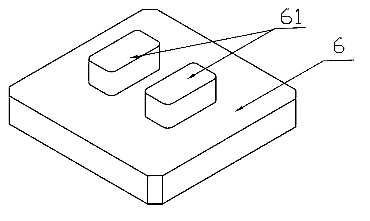
[0021] Embodiment: As shown in the figure, a linear moving device includes a stage 2 and a screw drive mechanism. The screw drive mechanism includes a screw 3, a screw nut 4 and a drive mechanism 5. The two sides of the screw 3 are respectively A linear guide rail 11 is provided, and a slider 12 is installed on the linear guide rail 11. The slider 12 is fixed to the stage 2, and an adjustment block 6 and a guide block 7 are arranged between the object stage 2 and the screw nut 4. The adjustment block 6 Fixed with the stage 2, the guide block 7 is fixed with the screw nut 4, and the adjustment block 6 is provided with two rectangular bumps 61 protruding to the guide block 7, and the two rectangular bumps 61 are arranged in sequence along the extending direction of the screw rod 2 The guide block 7 is provided with two rectangular guide grooves 71, and the rectangular protrusion 61 extends into the corresponding rectangular guide groove 71. In the direction perpendicular to the e...


PUM


Abstract

The invention discloses a linear moving device, which comprises a loading platform and a screw drive mechanism. The screw drive mechanism comprises a screw, a screw nut and a drive mechanism, two sides of the screw are respectively provided with a linear guide rail, a sliding block is arranged on the linear guide rails and is fixedly connected with the loading platform, an adjusting block and a guide block are arranged between the loading platform and the screw nut, the adjusting block is fixedly connected with the loading platform, the guide block is fixedly connected with the screw nut, the adjusting block is provided with at least one rectangular convex block protruding towards the guide block, the guide block is provided with at least one rectangular guide slot, the rectangular convex block extends into the rectangular guide slot, and the width of the rectangular guide slot is more than the width of the rectangular convex block in the direction vertical to extension of the screw. The linear moving device has the advantages that the accuracy of linear transmission can still be ensured when the screw is not parallel to the linear guide rails to certain degree.

Description

technical field [0001] The invention relates to a moving device, in particular to a linear moving device. Background technique [0002] With the development of industrial automation, linear moving devices are widely used in the field of automatic production or testing of products. Currently commonly used linear moving devices generally include a stage and a screw drive mechanism, and the screw drive mechanism includes a screw rod, a screw nut and a driving mechanism. The screw rod is threadedly connected with the screw nut, and the stage is fixedly installed on the screw nut. Both sides of the screw rod are respectively provided with linear guide rails, and a slider is installed on the linear guide rail. The slider is fixedly connected with the stage, and the slider supports the products on the stage. When the screw rotates, the screw nut moves linearly along the extension direction of the screw, and the products on the stage move linearly together under the drive of the s...

Claims


Application Information

Patent Timeline
Patent Type & Authority Applications(China)
IPC IPC(8): B65G35/00
Inventor 王刚赵高风
Owner NINGBO YUNSHENG INTELLIGENT TECHNOLOGY CO LTD
Why Eureka
Try Eureka