Three-position rotary transceiver

A transceiver device and rotary technology, applied in the direction of transportation, packaging, conveyors, etc., can solve the problems of low automation, occupying a lot of installation space, wasting raw materials, etc., and achieve the effect of high automation, less fault links and simple structure

Inactive Publication Date: 2013-04-03
银川东方气力运输设备有限公司
View PDF5 Cites 4 Cited by
  • Summary
  • Abstract
  • Description
  • Claims
  • Application Information

AI Technical Summary

Problems solved by technology

Using the above two methods to solve the problem of three-point transportation, there are problems such as wasting raw materials, greatly increasing equipment costs, occupying a lot of installation space, and low degree of automation.

Method used


Image

  • Three-position rotary transceiver
  • Three-position rotary transceiver
  • Three-position rotary transceiver

Examples


Embodiment Construction

[0014] The structure of the present invention will be described below in conjunction with the accompanying drawings.

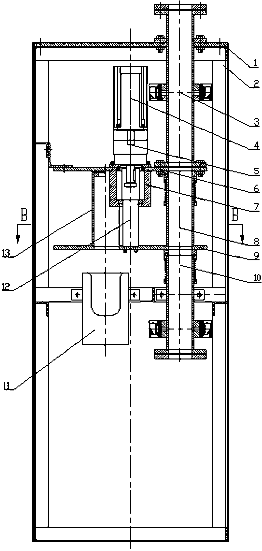
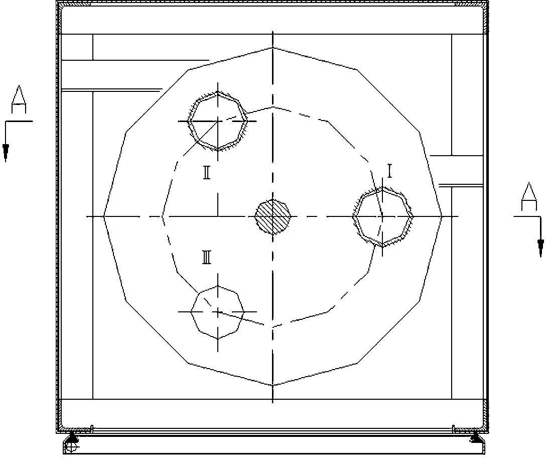
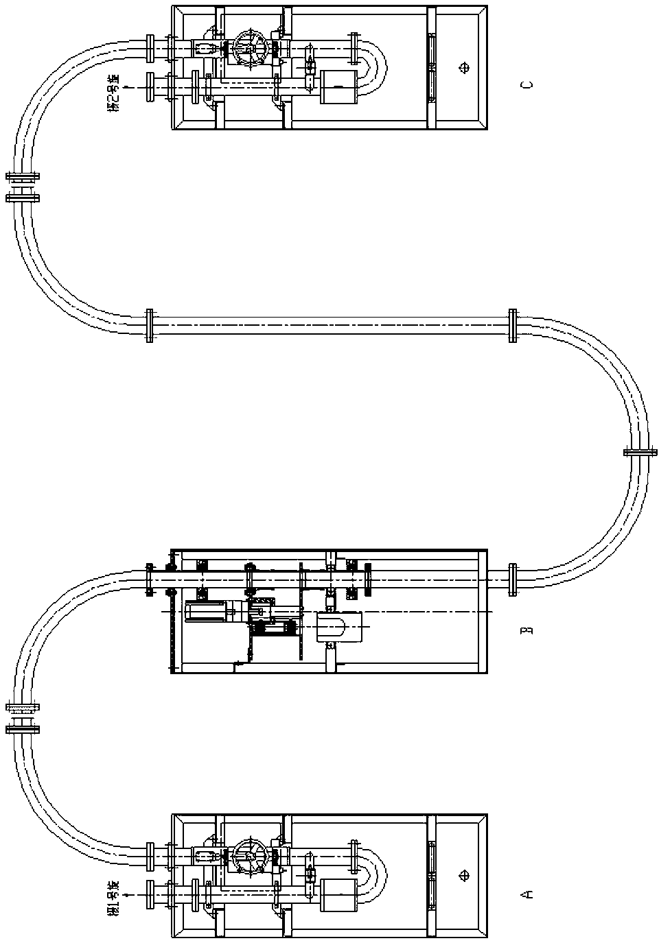
[0015] The three-station rotary transceiver device of the present invention includes a cabinet body 2 and a cover plate 1 installed on the cabinet body 2 . The upper plate 6 is fixedly installed in the cabinet body 2, the servo motor 4, the reducer 5 and the bearing support 6 are installed on the upper plate 6, and the connecting shaft 12 connected with the motor and the reducer main shaft is installed on the bearing support 6 , the connecting shaft 12 is fixed on the lower plate 9 . The lower plate 9 is disc-shaped, and three station holes are evenly distributed on it, and these three station holes are all connected with the upper pipe section 3 and the lower pipe section 10 installed in the cabinet body 2 after rotating under the drive of the servo motor 4. It is set concentrically and has the same inner diameter as the upper pipe section 3 and the lower pi...


PUM


Abstract

The invention relates to a three-position rotary transceiver, which comprises a cabinet body. The three-position rotary transceiver is characterized in that a lower plate which is uniformly provided with three position holes and can be rotated is arranged in the cabinet body, the three position holes are coaxially arranged with an upper pipe section and a lower pipe section which are installed in the cabinet body after the lower plate is rotated, wherein a No. I position middle pipe section is installed in the No. I position hole, a No. II position middle pipe section is installed in the No. II position hole, the upper end opening of the No. II position middle pipe section cannot pass through a container, and a container connecting box is installed below the No. II position middle pipe section. According to the three-position rotary transceiver, a servo motor is adopted as a driving device and controlled by a PLC (Programmable Logic Controller) of a whole system, the three-position rotary transceiver is rotated in accordance with a given instruction, and after the three-position rotary transceiver is rotated to a proper position, the three-position rotary transceiver is automatically shut down and braked. The three-position rotary transceiver which is directly driven by the servo motor has the advantages of less fault link, simple structure and high degree of automation.

Description

technical field [0001] The invention relates to a sending and receiving device of a pneumatic container conveying system, in particular to a three-station rotary sending and receiving device which can be installed in the middle of a conveying pipeline and send and receive containers. Background technique [0002] At present, in the pneumatic pipeline transportation system, the conventional equipment layout is to install a transceiver device at the beginning and end, and lay a transportation pipeline to realize one-to-one two-way transportation. In actual production operations, if two-way transportation between A and B, A and C is to be realized, two pipelines must be laid; if two-way transportation between A, B and C is to be realized, two Install 2 transceivers at site B, and use manual intervention to achieve this. Using the above two methods to solve the problem of three-point transportation has problems such as wasting raw materials, greatly increasing equipment costs, ...

Claims


Application Information

Patent Timeline
IPC IPC(8): B65G51/26
Inventor 苏伟慧姬承者陆学峰吴平良韩智伟权少波杜银学杨波麻寿宝贺登旭
Owner 银川东方气力运输设备有限公司
Why Eureka
Try Eureka