Automatic sequence gas filling disc special for gas filling substation

An automatic sequence, gas filling sub-station technology, applied in gas/liquid distribution and storage, pipeline systems, mechanical equipment, etc., can solve the problems of increased failure points, single method, high manufacturing and maintenance costs, and achieve reliable automatic opening, reducing The effect of failure links and reducing failure points

Inactive Publication Date: 2018-06-05
NINGBO FENGZHILI INFORMATION TECH CO LTD
View PDF0 Cites 0 Cited by
  • Summary
  • Abstract
  • Description
  • Claims
  • Application Information

AI Technical Summary

Problems solved by technology

At present, the method of controlling the sequential inflation through the sequence valve is single and the response speed is slow, resulting in a large safety hazard in the inflation process.
[0003] refer to figure 1 The traditional PLC parallel-connected automatic inflation sequence control panel shown is the gas distribution method required by most compressors when ordering. It is equipped with three one-way valves 7, two pneumatic ball valves 9, and two pneumatic ball valves. Composed of four pressure sensors 10, the PLC controller controls the solenoid valve on the pneumatic ball valve 9 according to the program instructions, and the switch of the pneumatic ball valve 9 is driven by a specially configured instrument air system. The components are scattered on the plane of the compressor base, and the structure is complex. , the control process is cumbersome, and the manufacturing and maintenance costs are high
At the same time, since the control panel is equipped with multiple electronic control components, the number of fault points increases, which is not conducive to the elimination of fault points

Method used


Image

  • Automatic sequence gas filling disc special for gas filling substation
  • Automatic sequence gas filling disc special for gas filling substation
  • Automatic sequence gas filling disc special for gas filling substation

Examples


Embodiment Construction

[0017] Below in conjunction with accompanying drawing and embodiment of description, the specific embodiment of the present invention is described in further detail:

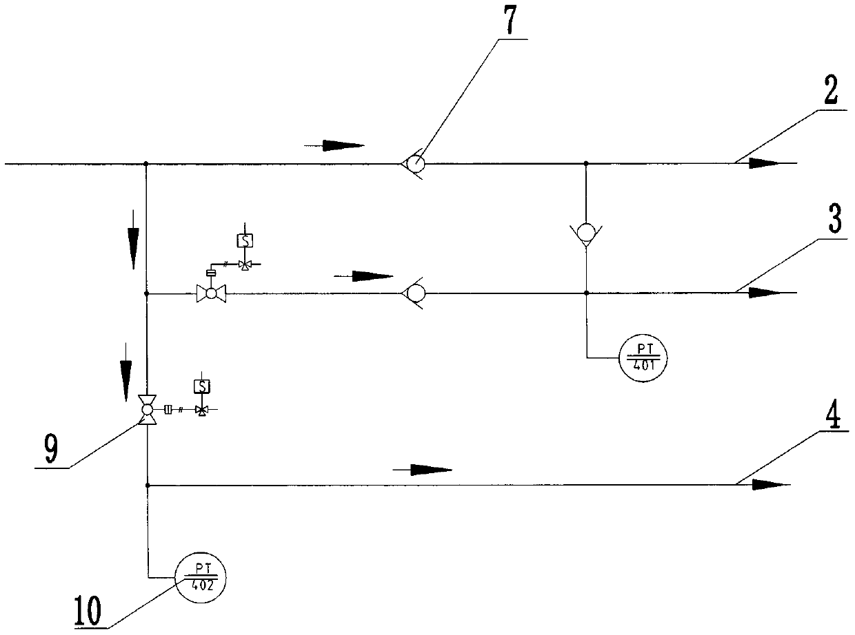
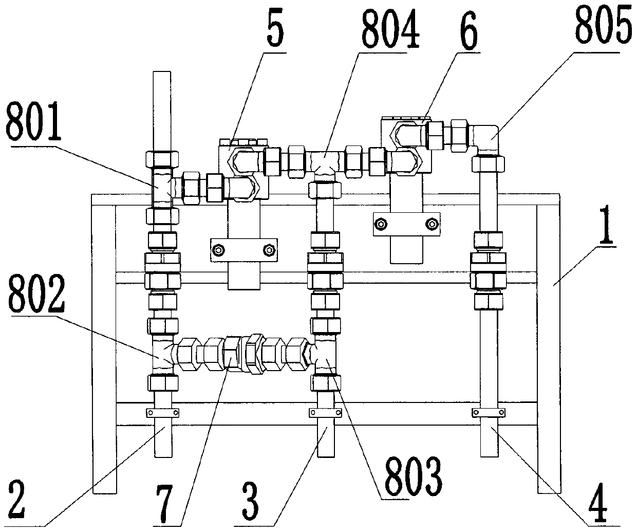
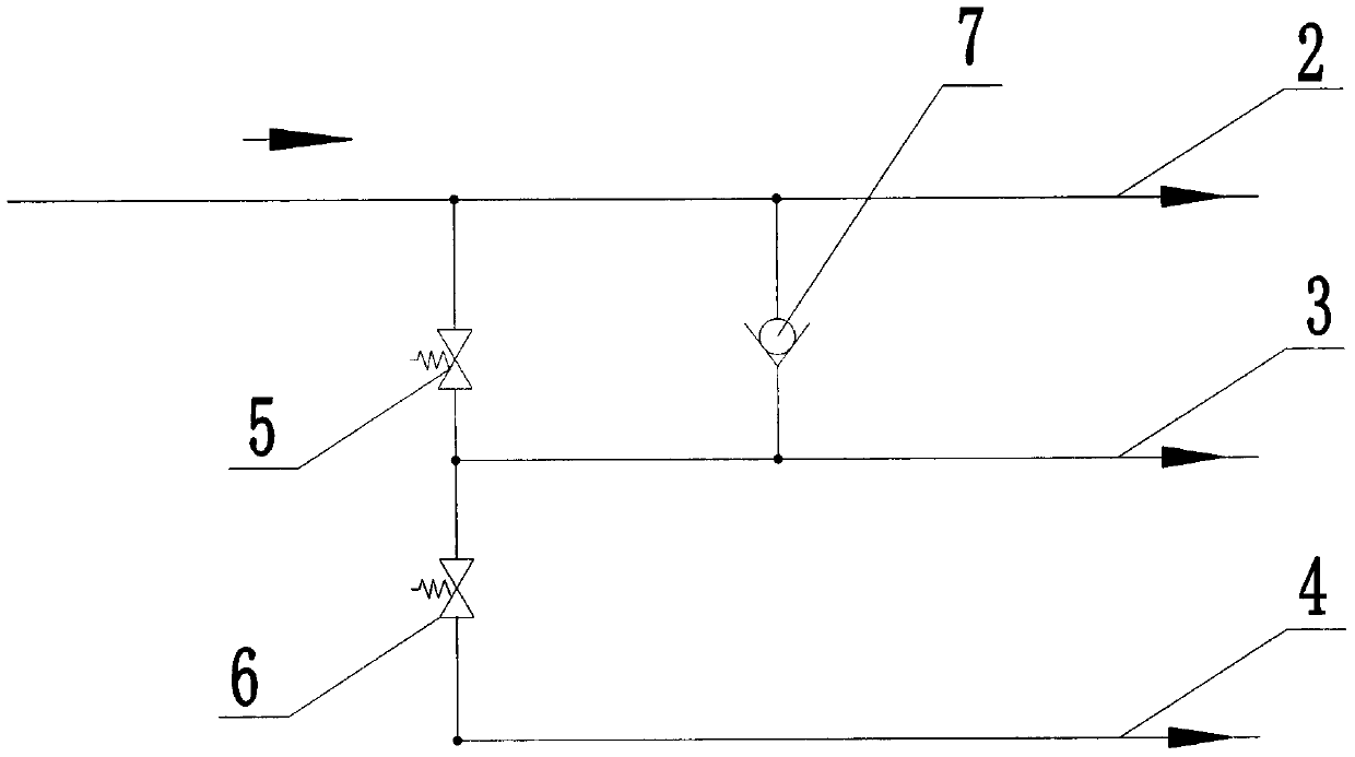
[0018] refer to figure 2 , image 3 with Figure 4 A kind of automatic sequence gas filling tray dedicated to the gas filling sub-station, including a bracket 1 and an inflation pipeline installed on the bracket 1, a self-operated high-pressure sequence valve 5, a self-operated medium-pressure sequence valve 6 and a one-way valve 7. The pipeline includes a direct charging pipeline 2, a high-pressure inflation pipeline 3 and a medium-pressure inflation pipeline 4; the direct charging pipeline 2 is provided with an air inlet joint, a No. 1 tee 801, a connecting pipe fitting, a No. Pass 802 and outlet joint; Described high-pressure inflation pipeline 3 is provided with inlet joint, connecting pipe fittings, No. 3 tee 803 and outlet joint successively from input end to output end; The output end is provided with...


PUM


Abstract

The invention relates to the technical field of gas inflation control, in particular to an automatic sequence gas filling disc special for a gas filling substation. The gas filling disc comprises a support, and further comprises air inflation pipelines, a self-operated high-pressure sequence valve, a self-operated medium-pressure sequence valve and a one-way valve which are arranged on the support, and the inflation pipelines comprise a straight inflation pipeline, a high-pressure inflation pipeline and a medium-pressure inflation pipeline; an output end of the self-operated high-pressure sequence valve is connected to an input end of the high-pressure air inflation pipeline; an input end of the self-operated high-pressure sequence valve is connected to an input end of the straight inflation pipeline; an input end of the self-operated medium-pressure sequence valve is connected to an input end of the medium-pressure air inflation pipeline; an input end of the one-way valve is connectedto an output end of the high-pressure air inflation pipeline; and an output end of the one-way valve is connected to an output end of the straight inflation pipeline. The gas filling disc has the advantages of being simple in structure and few in fault points.

Description

technical field [0001] The invention relates to the technical field of gas filling control, in particular to an automatic sequential filling plate dedicated to filling sub-stations. Background technique [0002] Parallel automatic inflation sequence control panel, its function is to directly enter the compressed natural gas into the sequence inflation pipeline. The parallel automatic inflation sequence control panel usually includes one or three sequential inflation pipelines with different pressures. When there is only one sequential inflation pipeline, a direct filling pipeline must be connected in parallel at the same time. When two or more sequential inflation pipelines are set in parallel , the direct charging pipeline can be set according to the needs. When the pressure of the natural gas discharged from the compressor reaches the set pressure of the high-pressure group, the sequence valve of the high-pressure group pipeline is first opened to inflate the high-pressur...

Claims


Application Information

Patent Timeline
Patent Type & Authority Applications(China)
IPC IPC(8): F17D1/04F17D3/01
CPCF17D1/04F17D3/01
Inventor 杨督
Owner NINGBO FENGZHILI INFORMATION TECH CO LTD
Why Eureka
Try Eureka