Gasifying method for biomass gasifier and hearth air intake device

A technology for air inlet devices and gasifiers, which is applied in the field of household furnaces or stoves. It can solve the problems of uneven wind field and wind pressure in the furnace, easy to generate slagging, and the inability of the gasifier to work continuously for a long time, so as to prevent air ducts Clogging, uniform wind pressure, and uniform temperature effects

Active Publication Date: 2013-04-03
孙吉章
View PDF8 Cites 7 Cited by
  • Summary
  • Abstract
  • Description
  • Claims
  • Application Information

AI Technical Summary

Problems solved by technology

[0002] At present, the fixed-bed biomass gasifier blasts the fuel through the furnace bridge or the air inlet of the furnace wall, which will cause uneven wind field and wind pressure in the furnace. If the stove is to work normally, the uneven wind field and wind pressure in the f...

Method used


Image

  • Gasifying method for biomass gasifier and hearth air intake device
  • Gasifying method for biomass gasifier and hearth air intake device
  • Gasifying method for biomass gasifier and hearth air intake device

Examples


Embodiment 1

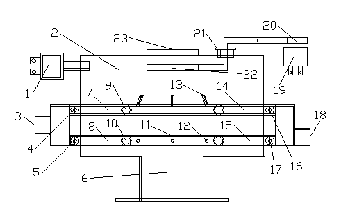
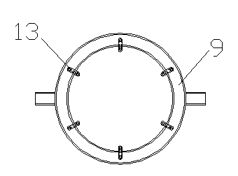
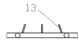
[0023] Embodiment 1: The furnace air inlet device is located above the furnace feed port 6, below the igniter 1 and the material level detection plate 22, the material level detection plate 22 is located directly below the gas outlet 23, and the annular air duct is located at the furnace 2 Inside, it is divided into an upper annular air duct 9 and a lower annular air duct 10. The radial end of the upper annular air duct 9 is connected to the air inlet 3 through the upper air duct air inlet pipe 7 and the upper air duct air inlet valve 4. The upper air duct The other end of the radial direction of the annular air duct 9 is connected to the sewage outlet 18 through the upper air duct blowdown pipe 14 and the upper air duct blowdown valve 16; The same end of the same) is connected to the air inlet 3 through the air inlet pipe 8 of the lower air duct and the air inlet valve 5 of the lower air duct. 17 is connected with sewage outlet 18. Air inlet 3, upper air duct air inlet valve...


PUM


Abstract

The invention discloses a gasifying method for biomass gasifier and a hearth air intake device. One or two combustion zones is/are arranged at the bottom of fuel and the air intake device has one or two zones; after a combustible is ignited, local combustion is formed at an air outlet of the air intake device; carbon dioxide generated after the local combustion contacts scorching fuel carbon on the upper layer and a reduction reaction is performed to generate combustible gas carbon monoxide; after gasification, the carbon monoxide is combusted again; when a biomass gasifier works normally, a combustible inlet is closed, the fuel is supplemented by feed and the carbon monoxide is further generated; when the air intake device has two zones, a reduction zone is arranged above a higher combustion zone; and when the biomass gasifier works normally, the combustible inlet is closed, the fuel is supplemented by feed and the carbon monoxide is further generated. The biomass gasifier is stable in gasification, can achieve a uniform wind field and wind pressure and can control the hearth temperature at 600-650 DEG C easily; and through design of a drain pipe, a drain valve and a drain port, blockage of an air passage can be prevented easily.

Description

technical field [0001] The invention belongs to a household stove or stove with solid fuel, and relates to a biomass gasification furnace gasification method and a furnace air inlet device. Background technique [0002] At present, the fixed-bed biomass gasifier blasts the fuel through the furnace bridge or the air inlet of the furnace wall, which will cause uneven wind field and wind pressure in the furnace. If the stove is to work normally, the uneven wind field and wind pressure in the furnace will cause The local temperature will exceed 800 degrees, which is easy to generate slagging (fuel slagging temperature is generally 680 degrees), because slagging will affect the ventilation performance of the furnace, so that the gasifier cannot work continuously for a long time. Therefore, a furnace air inlet device that can control the temperature of the furnace between 600 and 650 degrees and has a uniform wind field and pressure is needed to solve the slagging problem of the b...

Claims


Application Information

Patent Timeline
IPC IPC(8): C10J3/02C10J3/22C10J1/20F24B1/19
Inventor 孙清刚陆振邦
Owner 孙吉章
Why Eureka
Try Eureka