Spinning machine and method for discharging an end section of a thread on a spinning machine

A spinning machine and yarn technology, which is applied to spinning machines, open-end spinning machines, continuous winding spinning machines, etc., can solve the problems of unsuitable spinning process and delay.

Active Publication Date: 2013-04-03
MASCHINENFABRIK RIETER AG
View PDF8 Cites 15 Cited by
  • Summary
  • Abstract
  • Description
  • Claims
  • Application Information

AI Technical Summary

Problems solved by technology

In addition, it is usually necessary to remove certain sections of the yarn before spinning again, because the current yarn end is usually not suitable for the spinning process
Consequently, there is finally a significant delay for the next spinning process, because usually the service mechanism (which first has to work in the area of ​​the relevant spinning stand) has to find the thread and then remove the end piece

Method used


Image

  • Spinning machine and method for discharging an end section of a thread on a spinning machine
  • Spinning machine and method for discharging an end section of a thread on a spinning machine
  • Spinning machine and method for discharging an end section of a thread on a spinning machine

Examples


Embodiment Construction

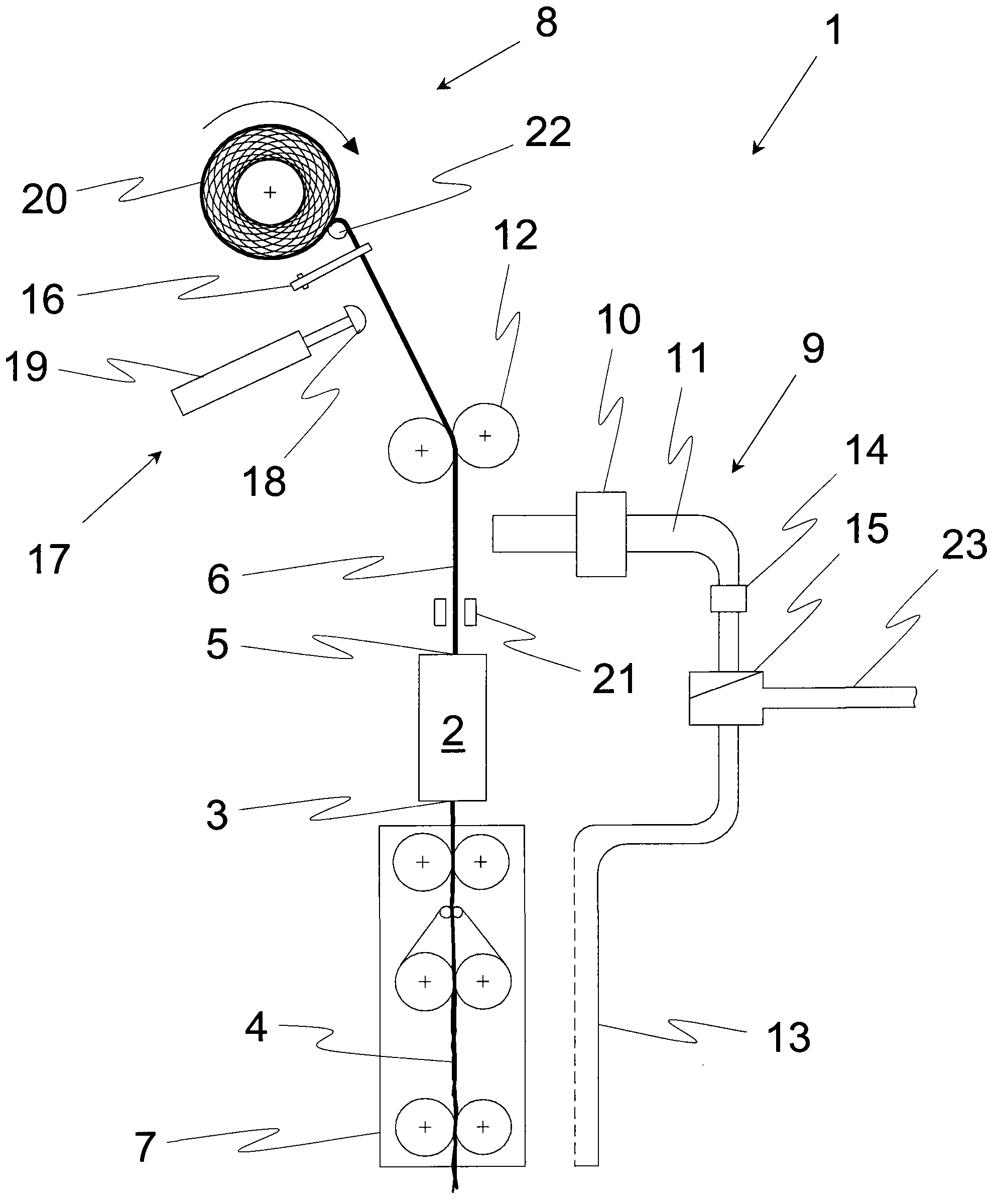
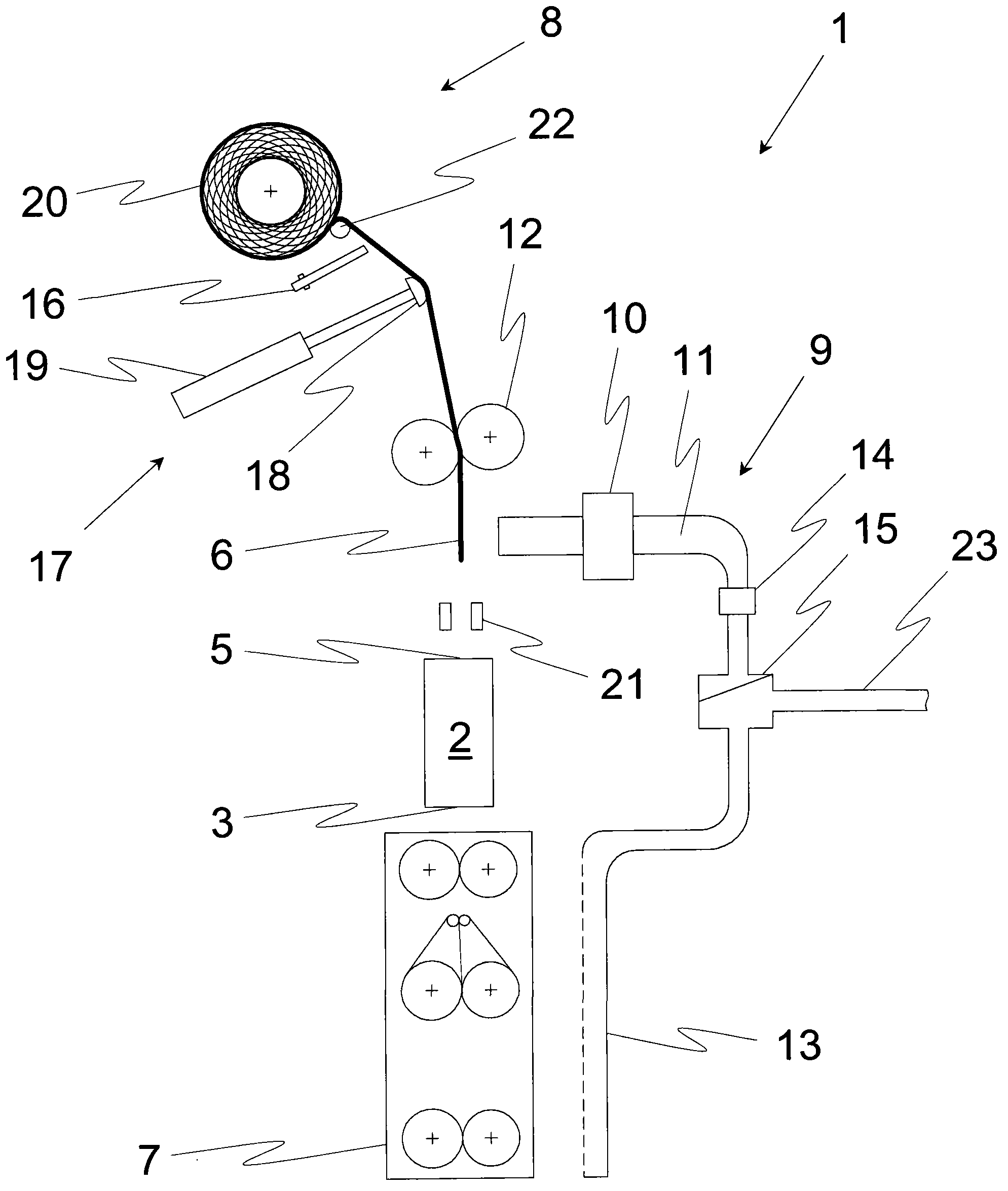
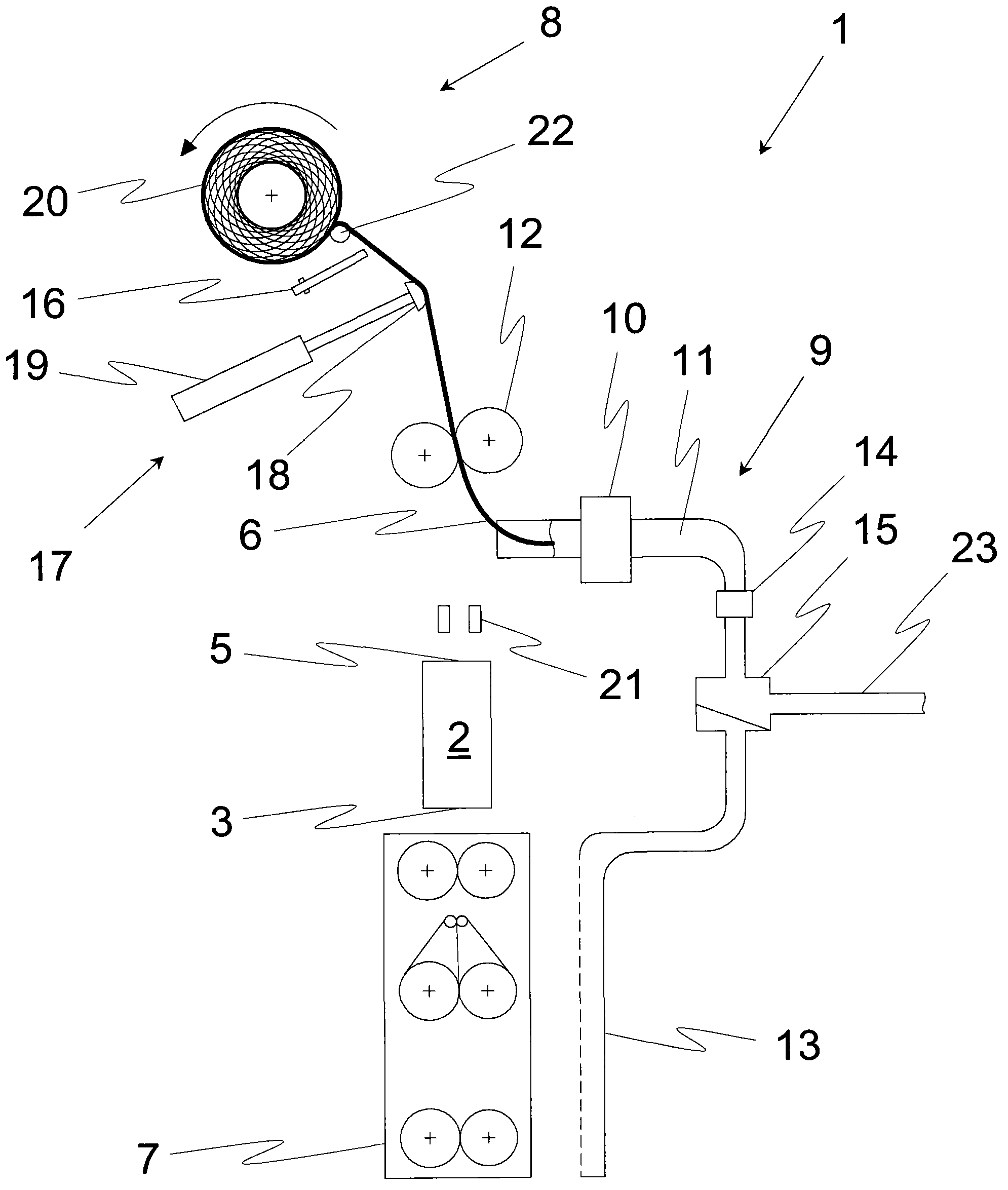
[0039] figure 1 A schematic side view showing the spinning table of a dry spinning machine (as an example of a spinning machine according to the invention) during spinning, wherein the dry spinning machine generally comprises a plurality of continuous perpendicular to the projection plane The spinning station 1 is arranged and preferably similarly assembled.

[0040] exist figure 1 In the example shown, the dry spinning machine has a conveying device 7 designed as a drafting device, which conveys the fiber material 4, for example, in the form of a double-line belt. Furthermore, the shown spinning station 1 comprises a spinning device 2 which is separated from the conveying device 7 and has an input 3 for the fiber material 4 and an inner vortex chamber, not shown.

[0041] Finally, the fibrous material 4 or at least a part of the fibers of the fibrous material 4 is made into the desired yarn 6 inside the vortex chamber by rotation in a known manner. In this case, the rotati...


PUM


Abstract

The invention relates to at least one spinning machine of a spinning table. The spinning point comprises a spinning device which has an input end for fiber material, an output end for yarn manufactured in the spinning device with the fiber material, a conveyance device used for guiding the fiber material to the spinning device, and a winding device for winding the manufactured yarn. The spinning point comprises a yarn end disposal means partly arranged between the input end of the yarning device and the winding device, and with the aid of which an end section of the produced yarn is able to be separated from the rest of the yarn and eliminated. Furthermore, a method for removing an end section of a yarn at a spinning point of a spinning machine prior to the subsequent piecing process is proposed. An end section of a yarn is obtained with the aid of the yarn end disposal means which is a constituent part of the spinning point. The end sections of yarn is disposed from an area of the spinning point after end sections of the rest yarns are separated, and the yarn end disposal means is at least partly arranged between the output end of the spinning device and the winding device.

Description

technical field [0001] The invention relates to a spinning machine with at least one spinning table, wherein the spinning table comprises a spinning device with an input for a fiber material and for a yarn produced from the fiber material in the spinning device An output end of the thread, a conveying device for guiding the fiber material to the spinning device and a winding device for winding the produced yarn. Furthermore, a method for removing end pieces of yarn at a spinning table of a spinning machine prior to the next splicing process is disclosed, wherein the spinning table comprises a spinning device with an input for fiber material and an output end for the yarn produced from the fiber material in the spinning device, a transfer device for guiding the fiber material to the spinning device and a winding device for winding the produced yarn, and In this case, after the interruption of the yarn process, at least the end section of the yarn to be unloaded is released by ...

Claims


Application Information

Patent Timeline
Patent Type & Authority Applications(China)
IPC IPC(8): D01H4/40D01H4/48
CPCD01H15/00D01H1/24D01H5/68B65H57/28B65H63/036
Inventor 阿达尔贝特·斯蒂芬J·卢德韦策克G·沙夫勒
Owner MASCHINENFABRIK RIETER AG
Why Eureka
Try Eureka