Compound driving device of TBM cutting disc motor hydraulic motor

A technology of hydraulic motors and driving devices, which is applied in mining equipment, earthwork drilling, tunnels, etc., can solve problems such as small escape torque and waste of installed power of motors, and achieve improved utilization of installed power, wide range of speed regulation, and enhanced The effect of geological adaptation

Active Publication Date: 2013-04-03
ZHEJIANG UNIV
View PDF6 Cites 12 Cited by
  • Summary
  • Abstract
  • Description
  • Claims
  • Application Information

AI Technical Summary

Problems solved by technology

However, in high-speed excavation, the torque of the motor is very small relative to the escape torque, thus causing a waste of installed power of the motor

Method used


Image

  • Compound driving device of TBM cutting disc motor hydraulic motor
  • Compound driving device of TBM cutting disc motor hydraulic motor

Examples


Embodiment Construction

[0018] The present invention will be further described below in conjunction with drawings and embodiments.

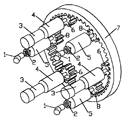
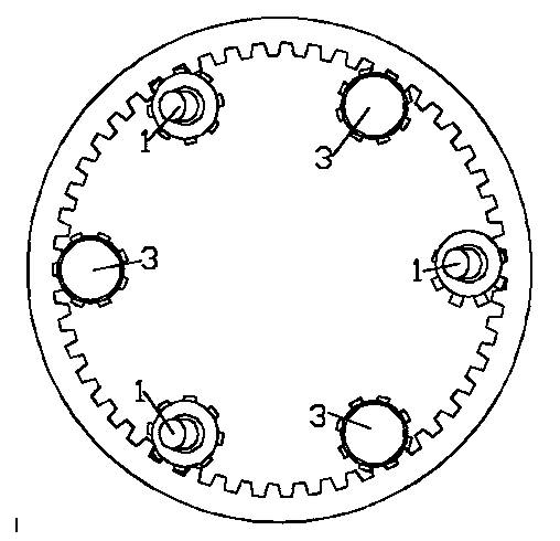
[0019] Such as figure 1 As shown, the TBM cutterhead motor-hydraulic-motor compound driving device is composed of a large ring gear 7, a variable frequency motor driving mechanism and a hydraulic motor driving mechanism.

[0020] The variable frequency motor drive mechanism comprises a variable frequency motor 3, a first speed reducer 4 and a first pinion 6, wherein the output shaft of the frequency conversion motor 3 is connected to the input shaft of the first speed reducer 4, and the output shaft of the first speed reducer 4 is connected to the first speed reducer 4. The pinion gear 6 is fixedly connected, and the first pinion gear 6 meshes with the large ring gear 7 .

[0021] The hydraulic motor drive mechanism includes a hydraulic motor 1, a viscous clutch 2, a second reducer 5, and a second pinion 8, wherein the output shaft of the hydraulic motor 1 is connected...


PUM


Abstract

The invention discloses a compound driving device of a hydraulic motor of a TBM (tunnel boring machine) cutting disc motor. The compound driving device comprises a big gear ring and a variable frequency motor driving mechanism, wherein the variable frequency motor driving mechanism comprises a first pinion, a first speed reducer and a variable frequency motor; the first pinion and the big gear ring are meshed; an output shaft of the first speed reducer and the first pinion are fixedly connected; an input shaft of the first speed reducer and an output shaft of the variable frequency motor are connected; in addition, the compound driving device also comprises a hydraulic motor driving mechanism, wherein the hydraulic motor driving mechanism comprises a second pinion, a second speed reducer, a viscosity clutch and a hydraulic motor; the second pinion and the big gear ring are meshed; an output shaft of the second speed reducer and the second pinion are fixedly connected; an input shaft of the second speed reducer and an output shaft of the viscosity clutch are connected; and an input shaft of the viscosity clutch and an output shaft of the hydraulic motor are connected. By utilizing the compound driving device, geological adaptability of a TBM cutting disc driving system and trouble-out ability of the TBM are obviously improved, so that driving characteristics of the cutting disc and geological characteristics of rock are matched, and the use ratio of the installed power is improved.

Description

technical field [0001] The invention relates to an electro-hydraulic compound drive technology, in particular to a drive device for a cutter head system of a full-face rock tunnel boring machine. Background technique [0002] The speed and torque characteristics of the full-face rock tunnel boring machine (hereinafter referred to as "TBM") under the actual tunneling conditions are as follows: if the TBM encounters soft soil during the tunneling process, under a small propulsion force, the cutterhead per revolution The axial propulsion of one revolution is relatively large. At this time, the actual load torque of the TBM is relatively large, and low-speed and high-torque excavation can be adopted. However, when encountering hard rock geology, even if the propulsion force is large, the cutterhead per revolution The axial penetration is still small, and the actual load torque is small. At this time, the rotating speed of the cutter head can be increased to realize high-spee...

Claims


Application Information

Patent Timeline
Patent Type & Authority Applications(China)
IPC IPC(8): E21D9/11
Inventor 谢海波洪啸庄莉杨华勇
Owner ZHEJIANG UNIV
Why Eureka
Try Eureka