Piston crown structure

A piston top and piston technology, applied to pistons, engine components, machines/engines, etc., can solve problems that are prone to damage and affect the service life of pistons

Inactive Publication Date: 2013-04-03
DALIAN BINCHENG PISTON MFG
View PDF0 Cites 7 Cited by
  • Summary
  • Abstract
  • Description
  • Claims
  • Application Information

AI Technical Summary

Problems solved by technology

[0002] In the prior art, the piston ring groove of the piston top structure cannot meet the working requirements of the piston in a relatively harsh environment, and is often prone to damage, which affects the service life of the piston

Method used


Image

  • Piston crown structure

Examples


Embodiment Construction

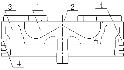
[0011] Such as figure 1 As shown, the piston top structure includes a combustion chamber 1, a valve avoidance cavity 2, an inner chamber 3 and a piston ring groove 4, the combustion chamber 1 is set on the upper part of the piston top, and the valve avoidance cavity 2 is arranged in four places evenly distributed around the top of the piston. The inner cavity 3 is set on the inner side of the piston top, and the piston ring groove 4 is set on the outer cylindrical surface of the piston top. There are 3 piston ring grooves 4, and the width of the piston ring groove 4 is 3.5 mm. The piston ring groove 4 is quenched by laser. In the piston top structure of the present invention, the piston ring groove adopts laser quenching, which can improve the surface hardness of the ring groove, improve the service life of the piston, and can be applied to occasions where the working environment is relatively harsh; the matrix structure is changed, and the focused laser beam is used for rapid ...


PUM


Abstract

The invention discloses a piston crown structure comprises a combustion chamber (1), valve avoidance holes (2), an inner cavity (3) and piston ring grooves (4), wherein the combustion chamber (1) is arranged at the upper part of the piston crown; the valve avoidance holes (2) are uniformly distributed on the circumference of the piston crown; the inner cavity (3) is formed in the inner side of the piston crown; the piston ring grooves (4) are formed in the outer cylindrical surface of the piston crown. According to the invention, the piston ring grooves adopt laser quenching to improve the surface hardness of the ring grooves and prolongs the service life of the piston, and can be suitable for occasions under abominable working environments.

Description

technical field [0001] The invention relates to a piston top structure. Background technique [0002] In the prior art, the piston ring groove of the piston top structure cannot meet the working requirements of the piston in a relatively harsh environment, and is often prone to damage, which affects the service life of the piston. Contents of the invention [0003] It is an object of the present invention to provide a piston crown structure with a long service life. [0004] The technical solution adopted by the present invention to achieve the above purpose is: a piston top structure, including a combustion chamber (1), a valve avoidance cavity (2), an inner cavity (3) and a piston ring groove (4), the combustion chamber (1) Set on the upper part of the piston top, the valve avoidance hole (2) is evenly distributed on the circumference of the piston top, the inner chamber (3) is set on the inner side of the piston top, and the piston ring groove (4) is set on the outside...

Claims


Application Information

Patent Timeline
Patent Type & Authority Applications(China)
IPC IPC(8): F02F3/26
Inventor 王景亮
Owner DALIAN BINCHENG PISTON MFG
Why Eureka
Try Eureka