Ejector and water heater with same

A technology of jet and water heater, applied in the field of water heater and solar water heater, can solve the problems of large installation space and unsightly appearance, and achieve the effect of solving the installation space

Active Publication Date: 2015-07-08
GUANGZHOU SEAGULL KITCHEN & BATH PROD
View PDF9 Cites 0 Cited by
  • Summary
  • Abstract
  • Description
  • Claims
  • Application Information

AI Technical Summary

Problems solved by technology

[0010] Therefore, the technical problem to be solved by the present invention is to overcome the large installation space and unsightly defects caused by the asymmetric distribution of the cold water inlet pipe and the hot water inlet pipe of the existing ejector, so as to improve the structure of the existing ejector , so that its hot water inlet pipe and cold water inlet pipe are distributed symmetrically

Method used


Image

  • Ejector and water heater with same
  • Ejector and water heater with same
  • Ejector and water heater with same

Examples


Embodiment 1

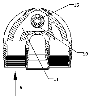
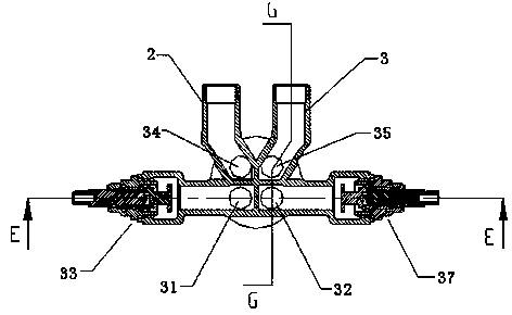
[0040] Such as Figure 1-Figure 3 As shown, this embodiment provides an eductor, including a shell body 1, the shell body 1 has a cold water chamber 11 adapted to communicate with the cold water inlet pipeline 2, and is located in the same plane as the cold water chamber 11 and A hot water chamber 12 with a common side wall and adapted to communicate with the hot water inlet pipeline 3, a jet channel 14 located on the common side wall and leading from the cold water chamber 11 to the hot water chamber 12 And the jet port 15 arranged at the end of the jet channel 14 at the hot water chamber 12, the diameter of the jet port 15 is smaller than that of the jet channel 14, and the jet port 15 communicates with the user port.

[0041] In this embodiment, the jet port 15 is a tapered hole, and the tapered hole passes the jet through the small opening. Of course, the jet port 15 can also be set in other regular or irregular shapes, as long as the diameter of the jet port 15 is smalle...

Embodiment 2

[0046] Such as Figure 9 , Figure 10 with Figure 11 As shown, this embodiment provides a schematic structural diagram of another ejector. The difference between this jet device and the jet device described in Embodiment 1 is: first, the jet injection port 15 is fixed on the jet channel 14 by bolts, and here, the bolt fixing is only a specific example of the detachable fixing method, The jet injection port 15 can also be fixed with the jet channel 14 in other detachable ways, for example, by screwing the jet injection port 15 with the jet channel 14 itself; The pipe 20 and the diameter reducing pipe 21 communicating with the throat pipe 20 flow to the user port. The diameter of the end of the diameter reducing pipe 21 facing the user port is large. A backup pressure is formed at the outlet of 21, so that a backflow phenomenon occurs after the negative pressure zone of the way is formed.

Embodiment 3

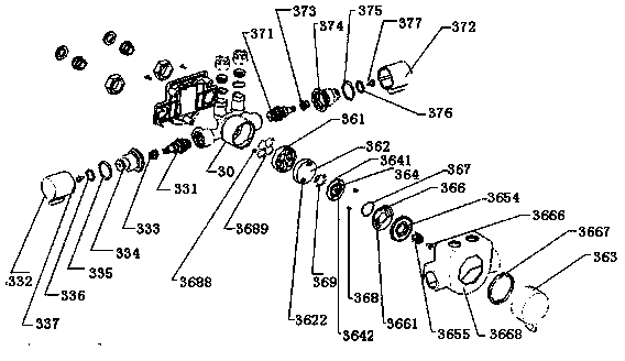
[0048] Such as Figure 4 As shown, the present embodiment is a drop-type solar water heater comprising the ejector described in Embodiment 1, the solar water heater mainly includes three parts, the first part is the ejector described in Embodiment 1, and the ejector The cold water chamber 11 and the hot water chamber 12 are adapted to communicate with the cold water inlet pipeline 2 and the hot water inlet pipeline 3 respectively; the second part is the cold water inlet pipeline communicated with the cold water chamber 11 and the hot water chamber The hot water inlet pipeline communicated with the chamber 12; the third part is able to communicate with the cold water inlet pipeline 2 and the hot water inlet pipeline 3, and is used to provide cold water and hot water to the ejector, and the flow rate of cold water and hot water And the double linkage control valve that controls the temperature of the mixed cold water and hot water.

[0049] The structure of the dual linkage con...


PUM


Abstract

The invention provides an ejector, which comprises a shell body, wherein the shell body is provided with a cold water cavity, a hot water cavity, an ejection passage and an ejection port; the cold water cavity is suitable for being communicated with a cold water inlet pipeline; the hot water cavity is positioned in the same plane as the cold water cavity, provided with a public side wall and suitable for being communicated with a hot water inlet pipeline; the ejection passage is positioned on the public side wall and leads to the hot water cavity from the cold water cavity; the ejection port is arranged in the ejection passage and positioned at one end of the hot water cavity; the aperture of the ejection port is less than that of the ejection passage; and the ejection port is communicated with a use port of a user. The ejector provided by the invention realizes ejection under the condition of symmetrical distribution of a hot water inlet pipe and a cold water inlet pipe.

Description

technical field [0001] The invention relates to a jet device and a water heater with the jet device, belonging to the technical field of solar water heaters. Background technique [0002] Existing solar water heaters mainly include pressure-bearing type and drop type. [0003] The working principle of the pressurized solar water heater is: the tap water enters the water tank and the heat pipe through the control switch, the heat collecting pipe absorbs the solar radiation and transfers the heat energy to the cold water in the heat pipe through the medium, and circulates the water in the water tank. Since the water tank is an overall closed structure, The cold water inlet must be opened during use, and the hot water in the water tank is pushed out with the hydraulic pressure of tap water, so that the hot water flows into the water unit from the water outlet. The water tank with this structure bears the pressure of tap water, the water flow rate is relatively large, and the ...

Claims


Application Information

Patent Timeline
Patent Type & Authority Patents(China)
IPC IPC(8): F04F5/10F04F5/44F24J2/46F24J2/40
CPCY02E10/40
Inventor 袁训平汤志强
Owner GUANGZHOU SEAGULL KITCHEN & BATH PROD
Why Eureka
Try Eureka