
Linear light source device and planar light source device

一种线性光源、平面光源的技术,应用在光源、电光源、光学元件等方向,能够解决平面光源器件庞大等问题,达到减小尺寸、增加亮度、增加光入射率的效果

Inactive Publication Date: 2013-04-03
TOYODA GOSEI CO LTD
View PDF9 Cites 2 Cited by
  • Summary
  • Abstract
  • Description
  • Claims
  • Application Information

AI Technical Summary

Problems solved by technology

[0011] As can be seen in Patent Reference 3, when a flexible substrate is used to connect with a power source and a planar light source device is configured through a linear light source device and a light guide plate, the planar light source device becomes bulky because there is an undesired flexible substrate part

Method used


Image

  • Linear light source device and planar light source device
  • Linear light source device and planar light source device
  • Linear light source device and planar light source device

Examples


Embodiment 1)

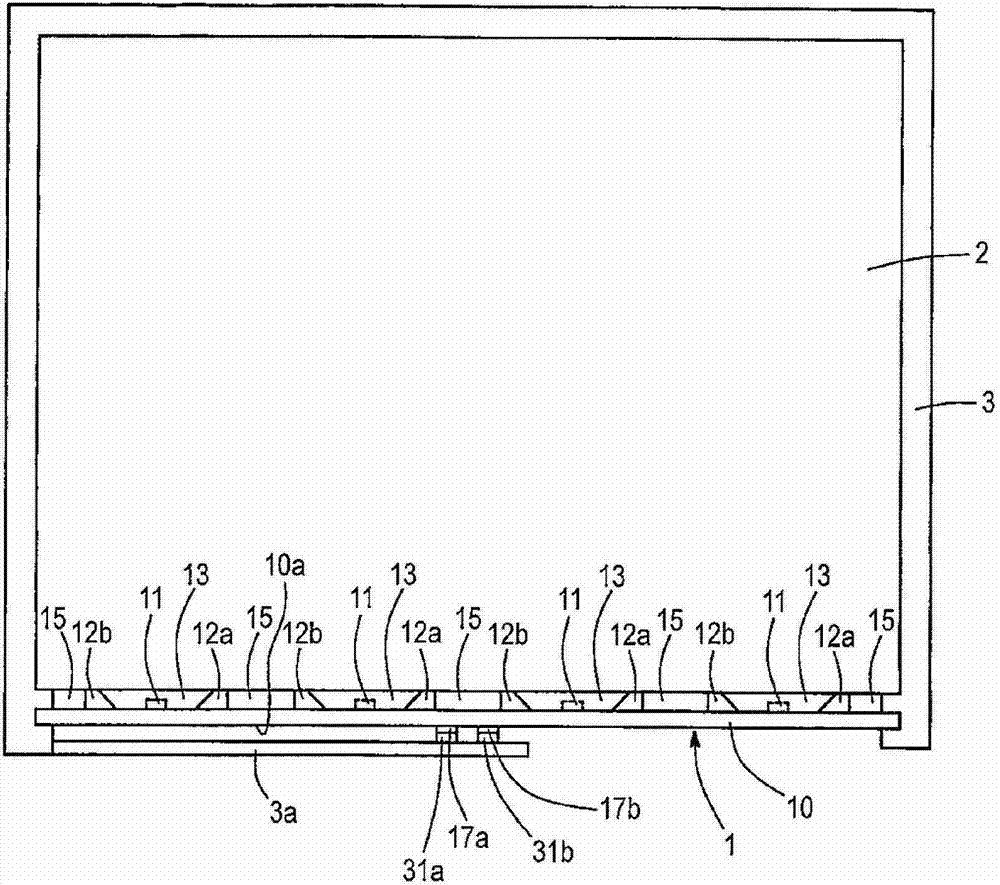
[0027] figure 1 is a diagram illustrating the configuration of the planar light source device in Embodiment 1. Such as figure 1 As shown in , the planar light source device includes a linear light source device 1 , a light guide plate 2 and a frame 3 . Here, the linear light source device 1 is arranged such that the linear light source device 1 has its light emitting direction toward the light guide plate 2 , and the linear light source device 1 is in contact with the side surface of the light guide plate 2 . The frame 3 has a structure in which the light guide plate 2 and the linear light source device 1 are inserted so that the position of the linear light source device 1 is fixed relative to the light guide plate 2 .

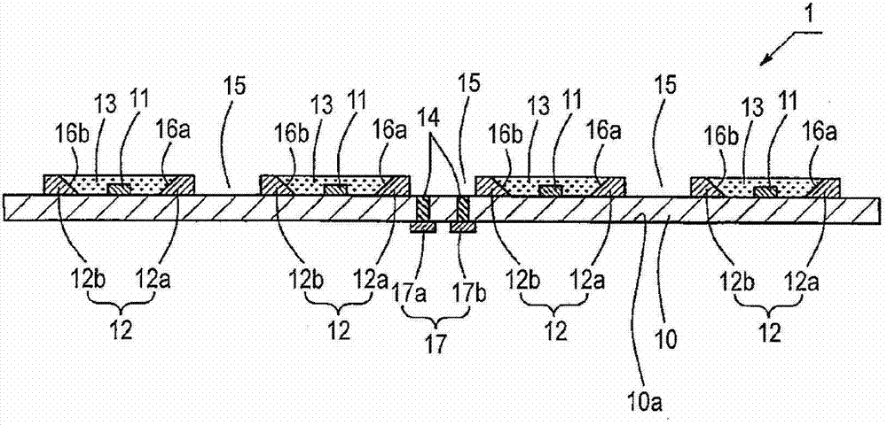
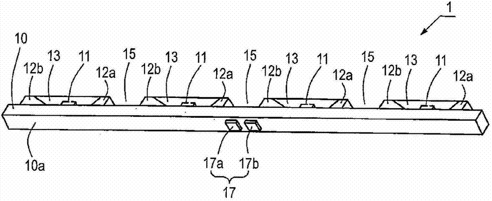
[0028] The configuration of the linear light source device 1 will be explained in more detail below. figure 2 is a sectional view illustrating the configuration of the linear light source device 1 . image 3 is a diagram illustrating the linear light sou...


PUM


Abstract

A linear light source device comprises a wiring substrate in a rectangular shape and having a wiring pattern formed thereon, a plurality of light emitting elements arranged on the wiring substrate in a longitudinal direction of the wiring substrate and connected with the wiring pattern on the wiring substrate, and a sealing resin that seals the light emitting elements, wherein the linear light source device is to be arranged on a side surface of a light guiding plate to form a planar light source device, and an external connection terminal is arranged on a surface of the wiring substrate that is opposite to a surface of the wiring substrate where the light emitting element are arranged and in a central portion in the longitudinal direction of the wiring substrate, and connected with the wiring pattern.

Description

technical field [0001] The present invention relates to a light source device having a plurality of light emitting elements arranged in a linear configuration and arranged on a side surface of a light guide plate for making a planar light source device. Background technique [0002] There is a planar light source device having a light guide plate and a linear light source device arranged on a side surface of the light guide plate (for example, see Patent Reference 1) as a liquid crystal display panel for use in a cellular phone or a digital camera or the like. [0003] The linear light source device includes: a printed circuit board having an elongated rectangular-shaped wiring pattern formed thereon; and connected to the wiring pattern of the printed circuit board; reflectors, which are respectively arranged on one side and the other side in the length direction of each light emitting element, and have inclined surfaces; and encapsulation resin, which is used to encapsulate...

Claims


Application Information

Patent Timeline
Patent Type & Authority Applications(China)
IPC IPC(8): F21S2/00F21V19/00F21V23/06F21Y101/02
CPCG02B6/0083G02B6/0068G02B6/0073
Inventor 国分英树伊藤优辉
Owner TOYODA GOSEI CO LTD
Learn More