Method and device for adjusting laser optical-channel focal length
A focus adjustment and optical path technology, applied in the field of optical instruments, can solve the problems of limited product processing accuracy and installation stability, focus deviation of receiving lens lens group and receiver, and lack of adjustability, etc.
- Summary
- Abstract
- Description
- Claims
- Application Information
AI Technical Summary
Problems solved by technology
Method used
Image
Examples
Embodiment 1
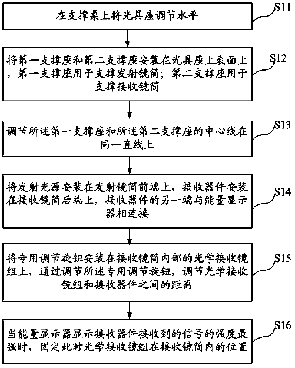
[0043] A method for adjusting the focal length of the laser light path disclosed in Embodiment 1 of the present invention, such as figure 1 As shown, it mainly includes the following steps:
[0044] Step S11: Adjust the level of the optical bench on the support table;
[0045] During the execution of step S11, the optical bench is fixed on the support table as a supporting body, and the optical bench is adjusted to be in a horizontal state, so as to ensure that the adjustment will not be deviated due to the inclination of the optical bench.
[0046] Step S12: Install the first support seat and the second support seat on the upper surface of the optical bench, the installation position of the first support seat corresponds to the position of the emission lens barrel in the laser analyzer, for Supporting the emitting lens barrel; the installation position of the second support seat corresponds to the position of the receiving lens barrel in the laser analyzer, and is used to su...
Embodiment 2
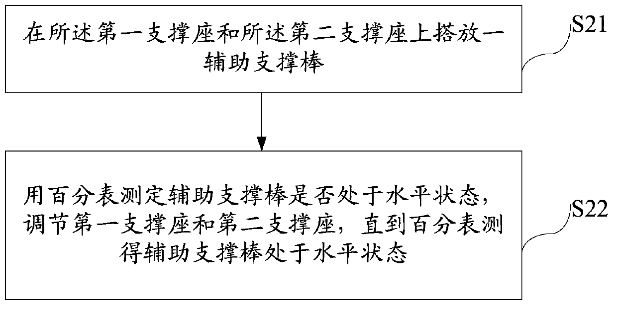
[0062] Based on the method for adjusting the focal length of the laser light path disclosed in the first embodiment above, on this basis, as figure 2 As shown, the process of adjusting the centerlines of the first support seat and the second support seat on the same straight line includes:
[0063] Step S21: placing an auxiliary support bar on the first support base and the second support base;
[0064] In the process of executing step S21, the auxiliary support rod is a standard rod whose size matches the outer dimensions of the emitting lens barrel and the receiving lens barrel. After installing the first support base and the second support base, the The auxiliary support rod is placed on the first support seat and the second support seat.
[0065] Step S22: Use a dial indicator to measure whether the auxiliary support bar is in a horizontal state, and adjust the first support seat and the second support seat until the dial indicator measures that the auxiliary support bar...
Embodiment 3
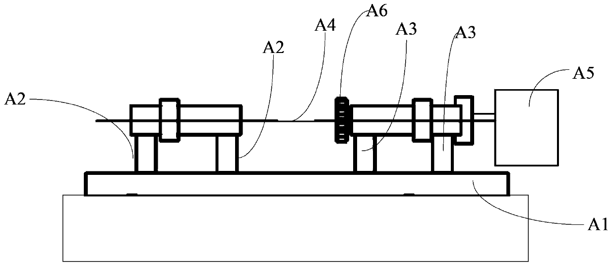
[0070] Embodiment 3 of the present invention discloses a laser light path focal length adjustment device, its structure is as follows image 3 As shown, it mainly includes: optical bench A1, first support base A2, second support base A3, adjustment device A4, energy display A5 and special adjustment knob A6.
[0071] Optical bench A1 installed horizontally on the support table;
[0072] Installed on the upper surface of the optical bench A1 to support the first support seat A2 of the emitting lens barrel in the laser analyzer, and installed on the upper surface of the optical bench A1 to support the laser analyzer The second support seat A3 of the receiving lens barrel, the installation position of the first support seat A2 corresponds to the position of the emission lens barrel in the laser analyzer; the installation position of the second support seat A3 corresponds to the position of the laser The position of the receiving lens barrel in the analyzer corresponds to;
[00...
PUM
 Abstract
Description
Claims
Application Information
 - R&D
- Intellectual Property
- Life Sciences
- Materials
- Tech Scout
- Unparalleled Data Quality
- Higher Quality Content
- 60% Fewer Hallucinations
Browse by: Latest US Patents, China's latest patents, Technical Efficacy Thesaurus, Application Domain, Technology Topic, Popular Technical Reports.
© 2025 PatSnap. All rights reserved.Legal|Privacy policy|Modern Slavery Act Transparency Statement|Sitemap|About US| Contact US: help@patsnap.com


