
A testing device for a liquid crystal module

A liquid crystal module and testing device technology, which is applied in the direction of instruments, static indicators, nonlinear optics, etc., can solve the problems of large errors and low test accuracy, and achieve the effect of narrowing the adjustment range, convenient adjustment, and rapid adjustment

Inactive Publication Date: 2015-11-11
BOE TECH GRP CO LTD +1
View PDF5 Cites 0 Cited by
  • Summary
  • Abstract
  • Description
  • Claims
  • Application Information

AI Technical Summary

Problems solved by technology

[0005] The technical problem to be solved by the present invention is that the test flicker degree of the existing liquid crystal module is manually adjusted by adjusting the voltage and observed by human eyes, which has the defect of large error, which makes the test accuracy not high

Method used


Image

  • A testing device for a liquid crystal module
  • A testing device for a liquid crystal module
  • A testing device for a liquid crystal module

Examples


Embodiment Construction

[0028] In order to make the technical problems, technical solutions and advantages to be solved by the present invention clearer, the following will describe in detail with reference to the drawings and specific embodiments.

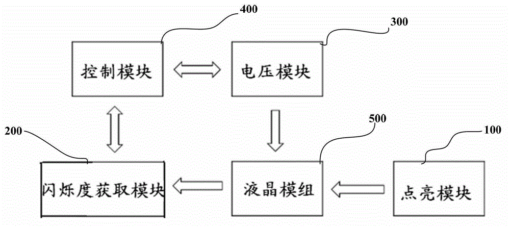
[0029] Such as figure 1 As shown, it is a schematic structural diagram of the test device of the first embodiment of the present invention. The test device of this embodiment includes a lighting module 100, a flicker acquisition module 200, a voltage module 300 and a control module 400, and the liquid crystal module 500 is used as the measuring unit. The lighting module 100 is used to connect with the liquid crystal module 500 to be tested to light the liquid crystal module and input a test picture. The scintillation acquisition module 200 is used to connect with the liquid crystal module 500 to be tested to acquire the scintillation of the liquid crystal module. The voltage module 300 is used to connect with the liquid crystal module to be tested and ...


PUM


Abstract

An embodiment of the present invention provides a test apparatus for a liquid crystal module, comprising: a light up module, being configured for being coupled to the liquid crystal module to be tested for lighting up the liquid crystal module, and providing a test image to the liquid crystal module; a flickering degree obtaining module, being configured for obtaining a flickering degree of the liquid crystal module; a voltage module, being configured for being coupled to the liquid crystal module to be tested, and supplying a voltage to the liquid crystal module; a control module, being respectively coupled to the flickering degree obtaining module and the voltage module, and being configured for controlling the voltage module to output the voltage and receiving the flickering degree of the liquid crystal module in association with the corresponding voltage obtained by the flickering degree obtaining module.

Description

technical field [0001] The invention relates to the testing field of liquid crystal modules, in particular to an automatic testing device for liquid crystal modules. Background technique [0002] Liquid Crystal Display (LCD, Liquid Crystal Display) has been widely used due to its light weight, power saving, and no radiation. The flicker of the liquid crystal display (Flicker) is due to the change caused by the fluctuation of the brightness on the same time axis. For this reason, the flickering degree of the liquid crystal module needs to be pre-adjusted before leaving the factory. [0003] In the current mainstream panel design, the voltage of the common electrode (Vcom) is fixed, and then the voltage of the display electrode is constantly switched up and down according to the gray scale. At the same time, under the influence of the feedback voltage, the optimal Vcom voltage drifts. On the flickering display of the LCD module, there is generally a special flicker screen, ...

Claims


Application Information

Patent Timeline
Patent Type & Authority Patents(China)
IPC IPC(8): G02F1/13
CPCG09G3/006G09G2320/0247
Inventor 张雄健
Owner BOE TECH GRP CO LTD
Learn More