Metal artifact correcting method of cone-beam CT (computed tomography) system

A technology of metal artifacts and correction methods, applied in the field of medical image processing, can solve the problems of increasing radiation dose of patients and prolonged scanning time of patients

Active Publication Date: 2013-04-03
SHENZHEN INST OF ADVANCED TECH
View PDF4 Cites 36 Cited by
  • Summary
  • Abstract
  • Description
  • Claims
  • Application Information

AI Technical Summary

Problems solved by technology

Due to the need to generate two CT image data sets at different energies, it is necessary to repeat the scan twice, which incr

Method used


Image

  • Metal artifact correcting method of cone-beam CT (computed tomography) system
  • Metal artifact correcting method of cone-beam CT (computed tomography) system

Examples


Embodiment Construction

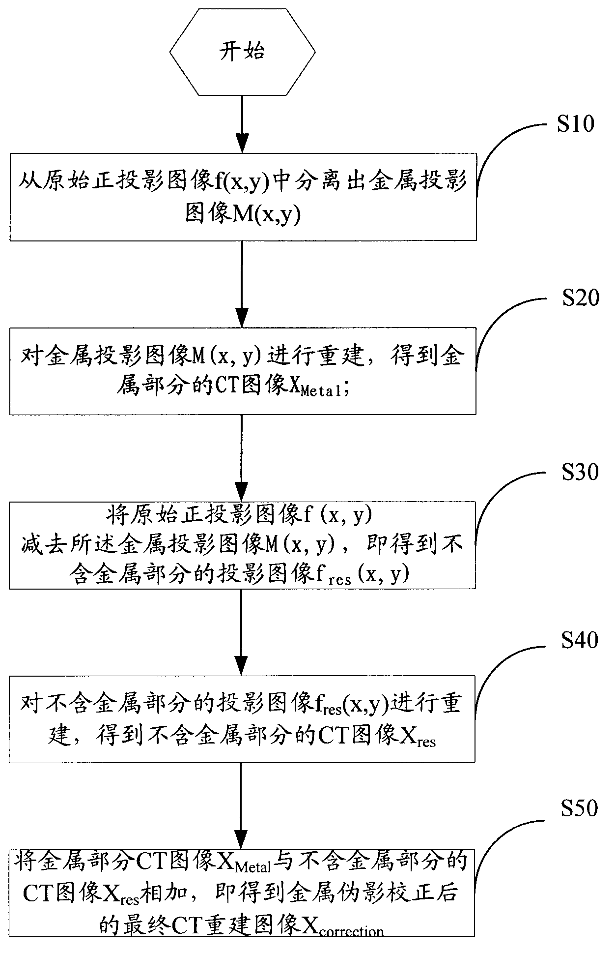
[0031] see figure 1 , a flow chart of the steps of the metal artifact correction method for the cone beam CT system provided by the embodiment of the present invention, including the following steps:

[0032] Step S10: Separate the metal projection image M(x, y) from the original orthographic projection image f(x, y).

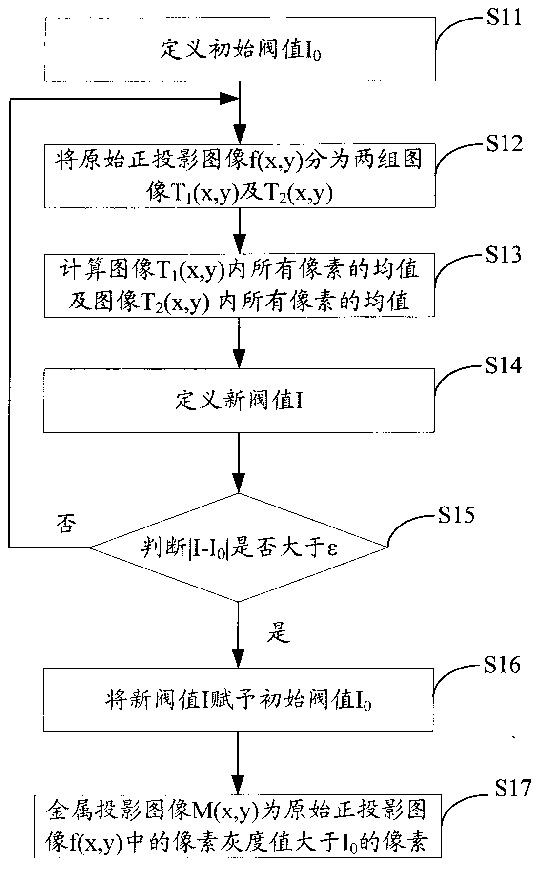
[0033] see figure 2 , is a flow chart of the steps for separating the metal projection image M(x, y) from the original orthographic projection image f(x, y) provided by the embodiment of the present invention, step S10 is specifically:

[0034] Step S11: Define the initial threshold I 0 . Among them, the initial threshold is I 0 =(I max +I min ) / 2, in the above formula, I max is the maximum gray value of the pixel in the original orthographic projection image f(x, y), I min is the minimum gray value in the original orthographic projection image f(x, y).

[0035] Step S12: Based on the initial threshold I 0 , divide the original orthographic projectio...


PUM


Abstract

The invention relates to a metal artifact correcting method of a cone-beam CT (computed tomography) system. The metal artifact correcting method of the cone-beam CT system comprises the steps of separating a metal projection image M (x, y) from an original orthographic projection image f(x, y), reconstructing the metal projection image M (x, y) to obtain a CT reconstruction image XMetal of the metal part, reducing the metal projection image M (x, y) of the original orthographic projection image f(x, y) to obtain a projection image fres(x, y) without the metal part, reconstructing the projection image fres(x, y) without the metal part to obtain a CT (computed tomography) image Xres without the metal part, and adding a CT (computed tomography) image Xmetal of the metal part with the CT (computed tomography) image Xres without the metal part to obtain a final CT (computed tomography) reconstruction image Xcorrection after the correction of a metal artifact. Coordinates are not changed in the metal artifact correcting method, so that the image space resolution is not lost, and the image quality is enhanced.

Description

technical field [0001] The invention relates to the field of medical image processing, in particular to a method for correcting metal artifacts of a cone-beam CT system. Background technique [0002] Cone beam CT (Computed Tomography) has developed rapidly in the fields of oral disease diagnosis, human local organ imaging, and industrial inspection due to its advantages of fast scanning speed, high ray utilization rate, low dose, and isotropic spatial resolution. However, the existence of substances with high attenuation coefficients in CT imaging (such as metal plastic devices in the human body, biopsy agents that patients must carry, metals in chips, etc.) will lead to serious metal artifacts, which appear as streaky bright lines, dark bands or Shadows seriously damage the authenticity of CT images, which greatly limits its high-precision detection in the medical and industrial fields. Therefore it is necessary to remove or minimize metal artifacts. [0003] Chinese Pate...

Claims


Application Information

Patent Timeline
IPC IPC(8): G06T5/50
Inventor 胡战利郑海荣夏丹
Owner SHENZHEN INST OF ADVANCED TECH
Why Eureka
Try Eureka