Operating mechanism controlling and protecting switching device

A technology of operating mechanism and protection switch, applied in the direction of protection switch operation/release mechanism, etc., can solve the problem of inability of the operation mechanism, and achieve the effects of avoiding false action, wide application range and stable work

Active Publication Date: 2014-11-05
浙江中凯科技股份有限公司
View PDF5 Cites 0 Cited by
  • Summary
  • Abstract
  • Description
  • Claims
  • Application Information

AI Technical Summary

Problems solved by technology

[0007] The technical problem to be solved by the present invention is that the existing operating mechanisms for controlling and protecting switching appliances cannot simultaneously realize the fire-fighting-type function of overloading, only alarming without tripping, alarming and tripping when over-current, and overloading and overloading of basic functions. Insufficiency of alarming and tripping during current flow, so as to provide a control that can be selected between the fire-fighting function of only alarming and not tripping when the current is overloaded, and the basic function of alarming and tripping when the current is overloaded with only one set of devices Operating mechanism with protective switch

Method used


Image

  • Operating mechanism controlling and protecting switching device
  • Operating mechanism controlling and protecting switching device
  • Operating mechanism controlling and protecting switching device

Examples


Embodiment 1

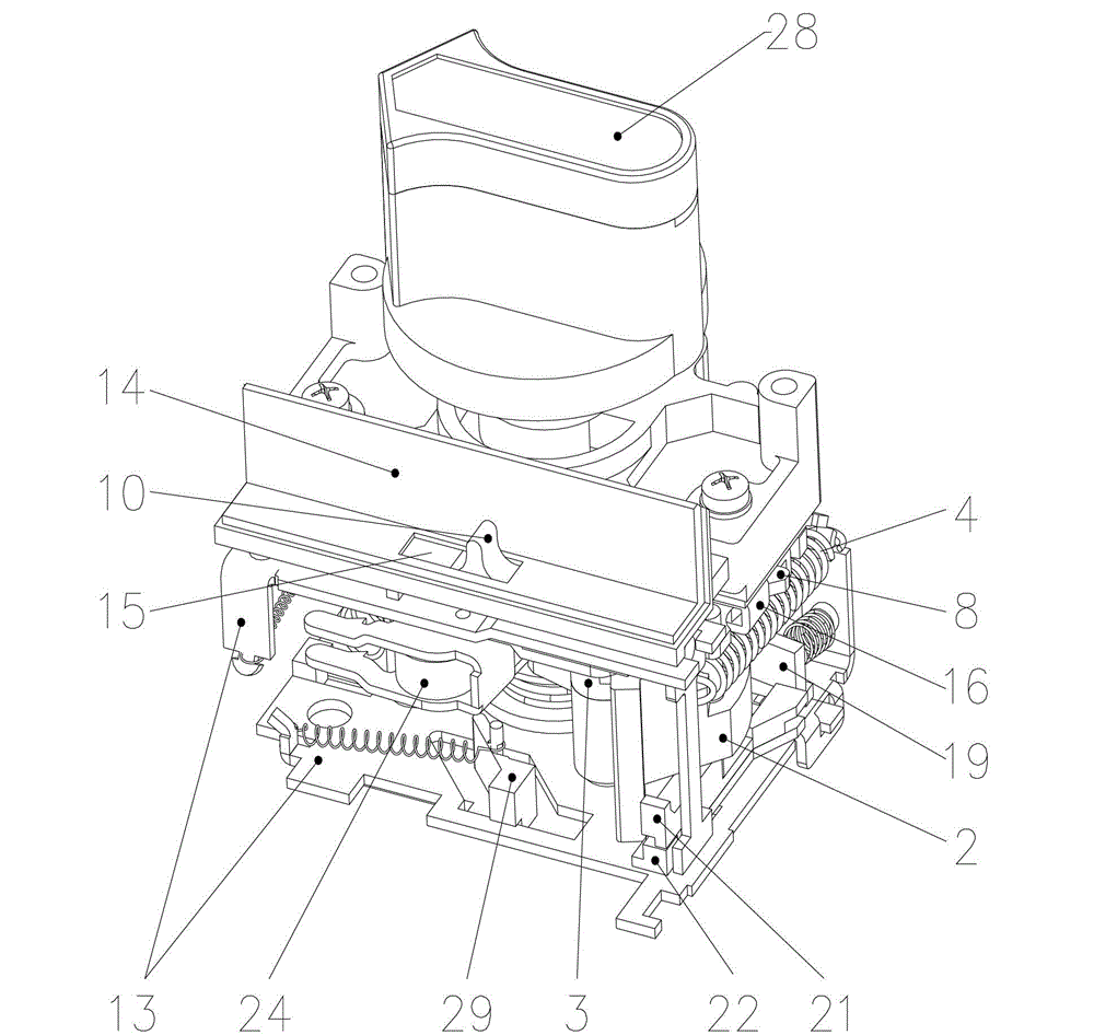
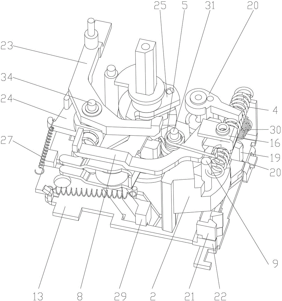
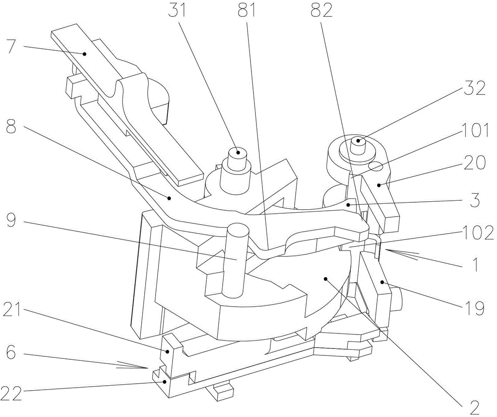
[0044] Such as figure 1 , 2 And as shown in 3, the operating mechanism of the control and protection switching device in Embodiment 1 includes an alarm tripping mechanism, a stopper 1, an alarm tripping push rod 6, a driving rod 7 and a tripping rod 8, wherein:

[0045] The alarm trip mechanism includes an alarm cam 2 for outputting an alarm signal and a trip cam 3 for outputting a trip signal.

[0046] The alarm cam 2 is rotatably mounted on the mounting plate 13 of the operating mechanism through a rotating shaft, and the alarm cam 2 is provided with an alarm card table 17 and a first device capable of driving the alarm cam 2 to rotate and reset to transmit an alarm signal. An elastic member 4 . The first elastic component 4 may be a spring.

[0047] The trip cam 3 is also rotatably mounted on the mounting plate 13 of the operating mechanism through a rotating shaft, the trip cam 3 is provided with a trip arm 18 and can drive the trip cam 3 to rotate and reset and then tr...

Embodiment 2

[0081] In this embodiment, the alarm stopper 19 and the tripping stopper 20 included in the stopper 1 are integrally formed, that is, the stopper 1 is provided with a The alarm stop boss 102 engaged or separated from the alarm card table 17 and the trip stop boss 101 engaged or separated from the trip arm 18 of the trip cam 3, wherein the trip The tripping time between the tripping brake boss 101 and the tripping cam 3 is greater than the tripping time between the alarm stopping boss 102 and the alarming cam 2 . Except for the above, other structures of the operating mechanism in this embodiment are the same as the operating mechanism in Embodiment 1, and will not be described in detail here.

[0082] The action principle of the stopper 1 is as follows:

[0083] When the shift lever 7 is in the fire-fighting position, the alarm push rod 6 receives the overload signal and moves to push the stopper 1 to rotate. Due to the tripping of the tripping brake boss 101 and the tripping...

Embodiment 3

[0086] In this embodiment, the alarm push rod 21 and the trip push rod 22 included in the alarm trip push rod 6 are integrally formed, that is, the alarm trip push rod 6 can not only receive an overload signal and move, but also It can move upon receiving an over-current signal. At this time, the travel of the alarm trip push rod 6 to receive the overload signal is smaller than the travel to receive the over-current signal. In addition, other structures of the operating mechanism in this embodiment are the same as those in Embodiment 1 or the operating mechanism in Embodiment 2, and will not be described in detail here.

[0087] The principle of action of the alarm trip push rod 6 is as follows:

[0088] When the shift lever 7 is in the fire-fighting position, the alarm trip push rod 6 receives the overload signal and moves and pushes the stopper 1 to rotate. The stroke that the overcurrent signal moves, the alarm cam 2 will trip and output the alarm signal, because the alarm...


PUM


Abstract

The invention discloses an operating mechanism controlling and protecting a switching device. The operating mechanism controlling and protecting the switching device comprises an alarm tripping mechanism including an alarm cam (2) and a tripping cam (3), a stop dog (1) provided with an alarm stop boss (102) and a tripping stop boss (101), an alarm tripping push rod (6) in contacted match with the stop dog (1) and receiving an overload signal or an overcurrent signal to drive the stop dog (1) to rotate, a poking rod (7) and a tripping rod (8). The tripping rod (8) rotates relative to the poking rod (7) and is in linkage with the poking rod (7), the poking rod (7) is provided with a fire protection device for overload alarm non-tripping and overcurrent alarm tripping and a basic device for overload alarm tripping and overcurrent alarm tripping. Only one set of operating mechanism can achieve selection between a fire protection function for alarming without tripping in current overload and a basic function for alarming and tripping in current overload while the volume for controlling and protecting the switching device is not increased.

Description

technical field [0001] The invention relates to the field of control and protection switching devices in low-voltage electrical appliances, in particular to an operating mechanism for controlling and protecting switching devices. Background technique [0002] "Control and Protective Switching Device" (or called Control Protective Device) is a new product in low-voltage electrical appliances. Its product category code is "CPS", which is the abbreviation of "Control and Protective Switching Device" in English. CPS can realize integrated, internally coordinated control and protection functions on products with a single structure, and can replace circuit breakers (fuse), contactors, overload (or overcurrent, phase failure) protection relays, starters, A variety of traditional discrete components such as isolators. KB0 is the first generation of CPS products in China. KB0 is mainly used in power systems with AC 50Hz (60Hz), rated voltage to 690V, and current from 0.16A to 125A ...

Claims


Application Information

Patent Timeline
Patent Type & Authority Patents(China)
IPC IPC(8): H01H71/10H01H71/12
Inventor 仇仙者杨佰传朱奇敏邱建洪黄世泽屠瑜权
Owner 浙江中凯科技股份有限公司
Why Eureka
Try Eureka