Coupled leakage cable

A leaky cable and coupling technology, applied in circuits, electrical components, leaky waveguide antennas, etc., can solve the problems of poor electrical performance of leaky cables, single insulation layer structure, etc., achieve good moisture resistance, excellent electrical performance, and reduce loss coefficient Effect

Inactive Publication Date: 2013-04-03
ZHEJIANG DETONG TECH
View PDF4 Cites 3 Cited by
  • Summary
  • Abstract
  • Description
  • Claims
  • Application Information

AI Technical Summary

Problems solved by technology

[0002] The coupled leaky cable is a cable whose outer conductor is not completely closed; during the transmission of the radio frequency signal in the leaky coaxial cable, part of it is coupled to the external space through the outer conductor hole, and the opposite external radio frequency signal can also be coupled to the cable through the outer conductor hole Internal; thus the leakage cable has dual functions, the transmission of radio frequency signals and the reception of the receiving antenna; it is mainly used in the weak and busy areas of the communication system, such as tunnels and subways; however, the insulation layer structure of the leakage cables in the prior art is relatively single , making the electrical performance of the leaky cable poor

Method used


Image

  • Coupled leakage cable
  • Coupled leakage cable

Examples


Embodiment 1

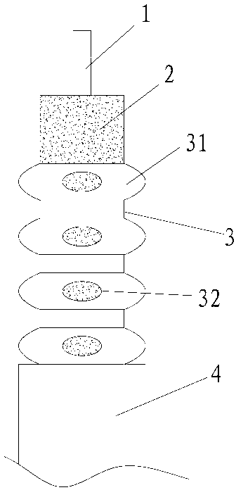
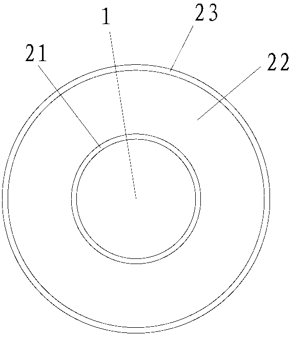
[0018] Embodiment 1: as Figure 1-2 As shown, a coupled leaky cable includes an inner conductor 1, an insulating layer 2 covering the inner conductor 1, an outer conductor 3 covering the insulating layer 2, and an outer conductor covering the outer conductor 3, the outer sheath 4, the outer conductor 3 has a plurality of smooth ring-shaped protrusions 31 distributed in parallel to make the outer conductor 3 wrinkled, each of the ring-shaped protrusions 31 has a smooth The insulating layer 2 includes an inner thin layer 21 covering the inner conductor 1, a foam layer 22 covering the inner thin layer 21, and an outer layer covering the foam layer 22. Thin layer 23; foaming degree of foam layer 22 ≥ 85%; distance between adjacent ring-shaped protrusions 31 is 7 mm; outer conductor 3 has a peak outer diameter of 24 mm and a wave trough outer diameter of 21 mm; inner conductor 1 The diameter is 10 mm; the outer diameter of the insulating layer 2 is 18 mm; the holes 32 are oval; th...

Embodiment 2

[0035] Embodiment 2: The difference with Embodiment 1 is that the distance between adjacent annular protrusions 31 is 5 mm; the outer diameter of the crest of the outer conductor 3 is 22 mm, and the outer diameter of the trough is 20 mm; the diameter of the inner conductor 1 is 8mm; the outer diameter of the insulating layer 2 is 14mm; the hole 32 is oval; the number of holes 32 on each annular protrusion 31 is 5, and they are evenly distributed.

[0036] The preparation method is similar to Example 1.

Embodiment 3

[0037] Embodiment 3: The difference with Embodiment 1 is that the distance between adjacent annular protrusions 31 is 10mm; the outer diameter of the crest of the outer conductor 3 is 25mm, and the outer diameter of the trough is 22mm; the diameter of the inner conductor 1 is 12 mm; the outer diameter of the insulating layer 2 is 20 mm; the holes 32 are oval; the number of holes 32 on each annular protrusion 31 is 6, and the holes 32 are evenly distributed.

[0038] The preparation method is similar to Example 1.


PUM


Abstract

The invention relates to the cable technology, in particular to a coupled leakage cable. The technical scheme includes that the coupled leakage cable comprises an inner conductor, an insulating layer coated outside the inner conductor, an outer conductor coated outside the insulating layer and a sheath coated outside the outer conductor, the outer conductor is provided with multiple smooth and parallel-distributed annular protrusions which enable the outer conductor to be winkled, each annular protrusion is provided with a smooth hole, and the insulating layer comprises an inner thin layer coated on the inner conductor, a foaming layer coated on the inner thin layer and an outer thin layer coated on the foaming layer. The coupled leakage cable has good electric performance.

Description

technical field [0001] The invention relates to cable technology, in particular to a coupling type leakage cable. Background technique [0002] The coupled leaky cable is a cable whose outer conductor is not completely closed; during the transmission of the radio frequency signal in the leaky coaxial cable, part of it is coupled to the external space through the outer conductor hole, and the opposite external radio frequency signal can also be coupled to the cable through the outer conductor hole Internal; thus the leakage cable has dual functions, the transmission of radio frequency signals and the reception of the receiving antenna; it is mainly used in the weak and busy areas of the communication system, such as tunnels and subways; however, the insulation layer structure of the leakage cables in the prior art is relatively single , making the electrical performance of the leakage cable poor. Contents of the invention [0003] The object of the present invention is to ...

Claims


Application Information

Patent Timeline
Patent Type & Authority Applications(China)
IPC IPC(8): H01P3/06H01P11/00H01Q13/20
Inventor 张祥金陈长军黄军武
Owner ZHEJIANG DETONG TECH
Why Eureka
Try Eureka