Transformer and iron core structure thereof

A technology of iron core column and iron yoke, applied in the field of transformers, can solve the problems of large iron core loss, high iron core loss, large iron core loss, etc.

Pending Publication Date: 2021-03-30
CSR ZHUZHOU ELECTRIC CO LTD
View PDF0 Cites 0 Cited by
  • Summary
  • Abstract
  • Description
  • Claims
  • Application Information

AI Technical Summary

Problems solved by technology

[0003] The core materials of medium and high frequency three-phase transformers in the prior art generally use nanocrystalline or ferrite with strong anti-saturation ability, low loss, and narrow and long hysteresis loops. In the manufacturing process, three single-phase iron cores are mainly used to form three-phase Iron core, or use a planar three-phase iron core; however, three single-phase iron cores are used to form a three-phase transformer. Symmetrical, it will bring problems such as unbalanced three-phase parameters, large core loss, high cost, high intermediate winding temperature, and inconsistent three-phase leakage inductance parameters.
Of course, there are also traditional three-dimensional iron core structures on the market. The materials generally use magnetically permeable silicon steel, amorphous alloys, nanocrystalline or ferrite. The entire iron core is composed of three identical single frames. After splicing, the three The core columns are arranged in an equilateral triangle; however, although the three-dimensional iron core structure is symmetrical, the three magnetic circuits are independent of each other, the loss coefficient is large, and the core loss is high. Therefore, a lower magnetic density has to be selected, resulting in an increase in cost
[0004] Therefore, how to avoid the increase in production cost due to the large core loss of the traditional core structure is a technical problem that those skilled in the art need to solve at present.

Method used


Image

  • Transformer and iron core structure thereof

Examples


Embodiment Construction

[0020] The following will clearly and completely describe the technical solutions in the embodiments of the present invention with reference to the accompanying drawings in the embodiments of the present invention. Obviously, the described embodiments are only some, not all, embodiments of the present invention. Based on the embodiments of the present invention, all other embodiments obtained by persons of ordinary skill in the art without making creative efforts belong to the protection scope of the present invention.

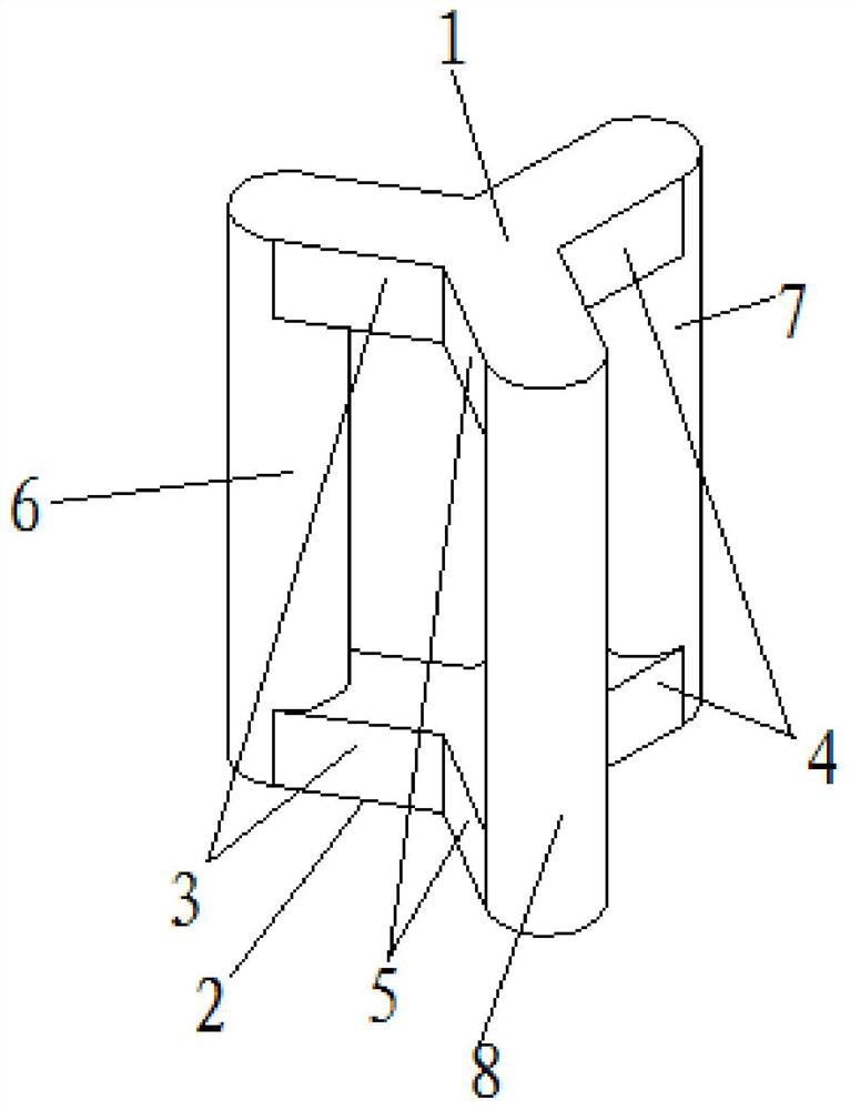
[0021] The core of the invention is to provide an iron core structure, which can make the magnetic circuits of the three-phase iron cores symmetrical, consistent in length and shortest; at the same time, it can ensure the non-independence of the three magnetic circuits, so that the loss coefficient is lower. Another core of the present invention is to provide a transformer comprising the above core structure.

[0022] In order to enable those skilled in the ar...


PUM


Abstract

The invention discloses a transformer and an iron core structure thereof. The iron core structure comprises an upper iron yoke, a lower iron yoke and three iron core columns arranged between the upperiron yoke and the lower iron yoke, the upper iron yoke and the lower iron yoke are both Y-shaped structures, and each Y-shaped structure comprises three connecting parts connected with the three ironcore columns in a one-to-one correspondence manner. Any iron core column is connected between the telecentric end of the connecting part of the upper iron yoke and the corresponding telecentric end of the connecting part of the lower iron yoke. According to the iron core structure, three-phase iron core magnetic circuits can be symmetrical and consistent in length, and the magnetic circuit is shortest; and meanwhile, the non-independence of the three magnetic circuits can be ensured, so that the loss coefficient is lower.

Description

technical field [0001] The invention relates to the technical field of transformers, in particular to an iron core structure. The invention also relates to a transformer with the core structure. Background technique [0002] At present, with the advancement of power electronics technology, the market has an increasingly strong demand for three-phase medium and high frequency transformers. Since the three-phase medium-high frequency transformer needs to have the characteristics of small size, low loss, light weight, low noise, and three-phase parameter balance, the iron core structure must have the advantages of small loss, low noise, and magnetic circuit symmetry in the medium-high frequency state. [0003] The core materials of medium and high frequency three-phase transformers in the prior art generally use nanocrystalline or ferrite with strong anti-saturation ability, low loss, and narrow and long hysteresis loops. In the manufacturing process, three single-phase iron c...

Claims


Application Information

Patent Timeline
Patent Type & Authority Applications(China)
IPC IPC(8): H01F27/26H01F27/255H01F27/34
CPCH01F27/255H01F27/263H01F27/266H01F27/34
Inventor 刘卓昌卢冬华李伟锋
Owner CSR ZHUZHOU ELECTRIC CO LTD
Why Eureka
Try Eureka