Electric valve

A technology for electric valves and valve housings, applied in valve details, valve devices, valve housing structures, etc., which can solve the problems of filter pressure loss, large minimum diameter, poor movement, etc., to reduce pressure loss and loss coefficient , The effect of preventing the intrusion of foreign matter

Active Publication Date: 2016-03-23
SAGINOMIYA SEISAKUSHO INC
View PDF5 Cites 0 Cited by
  • Summary
  • Abstract
  • Description
  • Claims
  • Application Information

AI Technical Summary

Problems solved by technology

However, in the case of processing by punching, although it can be processed at the same low cost as a drill, there is a problem that the minimum diameter that can be processed is large.
On the other hand, in the case of processing by etching or laser, it is possible to process smaller holes compared with processing by drilling or pressing, but there is a problem that the processing itself costs
[0015] In contrast, in the technology of Patent Document 2, although the filter can be used to reduce the intrusion of foreign matter, pressure loss occurs due to the filter, so there is a problem that the pressure equalization of the rotor chamber and the valve chamber becomes insufficient (expensive pressure equalization is required). time), and become the cause of poor movement

Method used


Image

  • Electric valve
  • Electric valve
  • Electric valve

Examples


Embodiment Construction

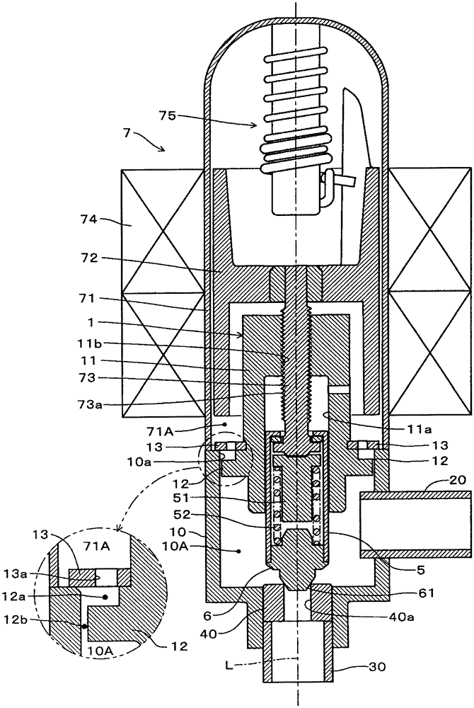
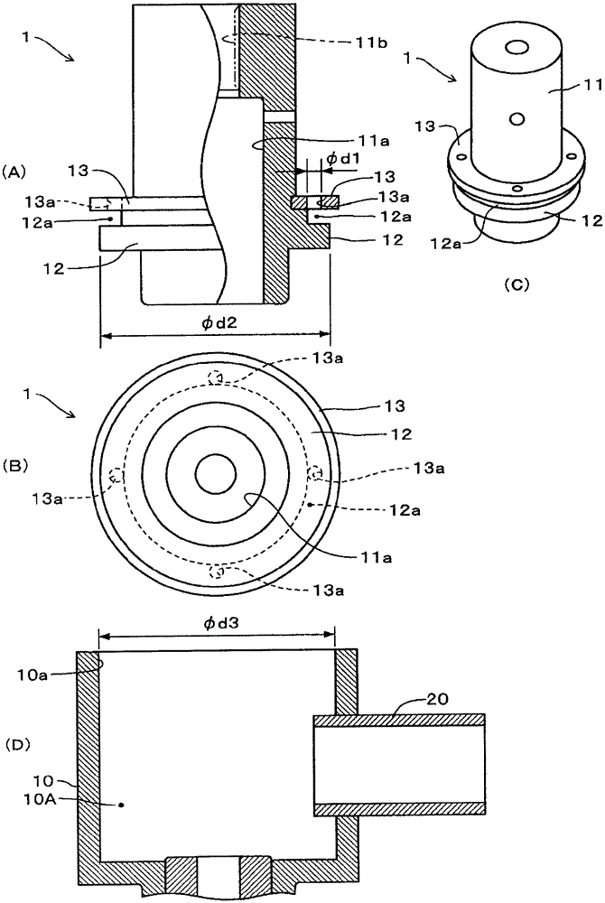
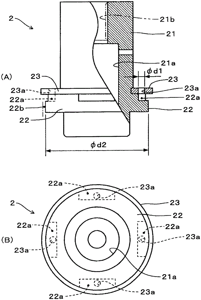
[0042] Next, an embodiment of an electric valve according to the present invention will be described with reference to the drawings. figure 1 It is a longitudinal sectional view and an enlarged sectional view of main parts of the electric valve according to the first embodiment, figure 2 It is a partially broken side view of the supporting member of the electric valve of the first embodiment ( figure 2 (A)), bottom view ( figure 2 (B)), perspective view ( figure 2 (C)) and the sectional view of the valve housing ( figure 2 (D)). image 3 It is a partially broken side view of the support member of the electric valve of the second embodiment ( image 3 (A)) and bottom view ( image 3 (B)). Figure 4 It is a partially cutaway side view of a supporting member of an electric valve according to a third embodiment ( Figure 4 (A)) and bottom view ( Figure 4 (B)). The following embodiments are the same as those described above Figure 5 and Figure 6 The difference of...


PUM


Abstract

PROBLEM TO BE SOLVED: To provide an electrically-driven valve having a foreign matter collecting mechanism, in the electrically-driven valve in which a rotor chamber and valve chamber are uniformly pressurized with a support member for supporting a rotor shaft.SOLUTION: The support member 1 is mounted on an opening 10a of a valve housing 10. A case 71 is firmly fixed on an end of the opening 10a by welding. A magnet rotor 72 is stored in the case 71. A female screw section 73a of the rotor shaft 73 is screwed with a male screw section 11b of a holder section 11 of the support member 1, and the rotor shaft 73 is supported by the support member 1. A gap 12b is formed by lessening a diameter of a circumference of a fitting section 12 of the support member 1 rather than an inner diameter of the valve housing 10. A diameter-reduced section 12a (recessed section) is formed at a flange 13 side of the fitting section 12. A communication hole 13a communicating with the diameter-reduced section 12a is formed on the flange 13.

Description

technical field [0001] The present invention relates to an electric valve installed in a refrigeration cycle of an air conditioner and the like to control the flow rate of refrigerant. Background technique [0002] Conventionally, the electric valve connected to the refrigeration cycle needs to ensure the airtightness of the entire refrigeration cycle, and a rotor such as a stepping motor as a drive unit is arranged in the rotor chamber and the rotor chamber is sealed together with the valve chamber. Such an electric valve is called "fixed type", and there are, for example, techniques disclosed in Japanese Utility Model Registration No. 3145048 (Patent Document 1) and Microfilm of Japanese Utility Model Laid-Open No. 2-48766 (Patent Document 2). [0003] In the electric valve of Patent Document 1, a valve seat is attached to a cylindrical valve housing, a support member is attached to an opening on the opposite side, and a valve body is fitted into a cylindrical hole of the ...

Claims


Application Information

Patent Timeline
Patent Type & Authority Patents(China)
IPC IPC(8): F16K31/04F16K27/00
CPCY02B30/70
Inventor 关口英树福安珠实平川尚
Owner SAGINOMIYA SEISAKUSHO INC
Why Eureka
Try Eureka