Broadband cavity-backed double-slot microstrip antenna

A microstrip antenna and double-slot technology, applied in slot antennas, antennas, resonant antennas, etc., can solve the problems of not being able to cover multiple standard wireless communication system frequency bands, complex directional antenna structures, and limited bandwidth, and achieve simple structure and low cost. Inexpensive, bandwidth-increasing effect

Inactive Publication Date: 2013-04-03
NANJING UNIV OF POSTS & TELECOMM
View PDF1 Cites 5 Cited by
  • Summary
  • Abstract
  • Description
  • Claims
  • Application Information

AI Technical Summary

Problems solved by technology

However, in the existing indoor communication signal coverage system, the structure of the directional antenna is complicated, the cost is high, and the bandwidth is limited, so it cannot cover the frequency bands of various wireless communication systems.

Method used


Image

  • Broadband cavity-backed double-slot microstrip antenna
  • Broadband cavity-backed double-slot microstrip antenna
  • Broadband cavity-backed double-slot microstrip antenna

Examples


Embodiment Construction

[0019] Below in conjunction with accompanying drawing, technical scheme of the present invention is described in further detail:

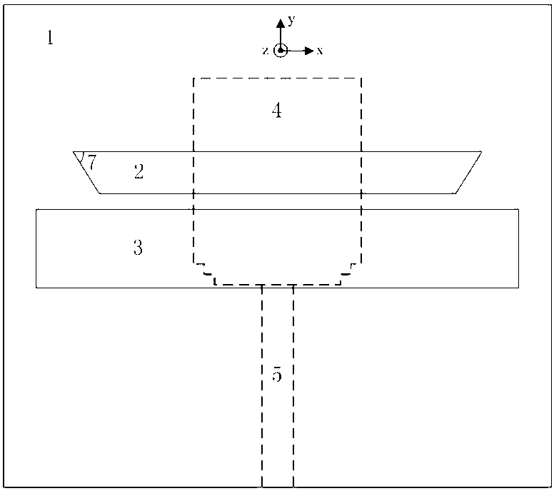
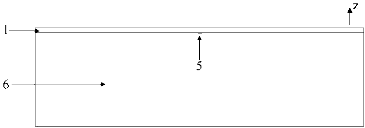
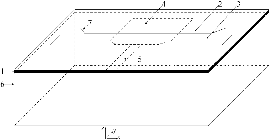
[0020] combine figure 1 , 2 , 3, the structure of the present invention is: the antenna is made on the dielectric substrate 1, the first slit 2, the second slit 3, the polygonal radiation patch 4, the microstrip feeder 5, and the metal back cavity 6 are symmetrical about the y-axis; the polygonal The radiation patch 4 is connected to the microstrip feeder 5 to form a feed structure; wherein, the metal back cavity 6 is a non-fully enclosed cuboid, which lacks an upper surface and a front end, and the dielectric substrate 1 serves as the upper surface of the metal back cavity , the non-closed front side is the side close to the microstrip feeder. The structural hierarchy of the present invention from top to bottom is the first slot 2 and the second slot 3 , the dielectric substrate 1 , the polygonal radiation patch 4 and the feeder 5 , and the meta...


PUM


Abstract

The invention discloses a broadband cavity-backed double-slot microstrip antenna which comprises a dielectric substrate (1) and a metal back cavity (6) equal to the dielectric substrate (1) in length and width. The metal back cavity (6) is a cuboid without the upper surface and the front surface, the top layer of the dielectric substrate (1) is a shielding conductor, a first slot (2) and a second slot (3) in mutually parallel are etched on the shielding conductor, the length of the first slot (2) is smaller than that of the second slot (3), a microstrip feeder line and a polygonal radiating patch are made on the bottom layer of the dielectric substrate, and the metal back cavity has a certain height and is connected with the shielding conductor, so that the antenna has directional radiating characteristics. Position, area and number of the slots, height of the cavity and the like have influences on performances of the antenna, so that a super-broadband directional antenna with better performances can be obtained by changing the structural parameters.

Description

technical field [0001] The invention relates to a broadband cavity-backed double-slot microstrip antenna, which belongs to the field of microwave technology. Background technique [0002] UWB communication technology originated from "impulse radio" in the late 19th century and early 20th century. In the past, UWB technology was generally used for underground target detection, electromagnetic flaw detection, nuclear radiation simulation and protection, etc. In recent years, with the continuous development of indoor short-distance wireless access technology, UWB communication technology has attracted much attention. It is generally believed that antennas with a relative bandwidth exceeding 25% are ultra-wideband antennas. On the other hand, with the rapid development of wireless communication, in order to meet the needs of indoor signal coverage and enhancement, directional antennas with high gain characteristics have been more and more widely used. However, in the existing...

Claims


Application Information

Patent Timeline
Patent Type & Authority Applications(China)
IPC IPC(8): H01Q9/04H01Q13/08H01Q13/10H01Q21/24
Inventor 吕文俊杨敬宇刘艳明朱洪波
Owner NANJING UNIV OF POSTS & TELECOMM
Why Eureka
Try Eureka