Automatic temperature-rising power transmission line system

A technology of automatic heating and power transmission lines, applied in the direction of circuits, power cables, electrical components, etc., can solve the problems of wire galloping, damage to power transmission facilities, energy waste, etc., and achieve the effects of reducing volume, simplifying connections, and facilitating operation and maintenance

Inactive Publication Date: 2013-04-03
西昌市世通配件加工厂
View PDF6 Cites 8 Cited by
  • Summary
  • Abstract
  • Description
  • Claims
  • Application Information

AI Technical Summary

Problems solved by technology

However, no matter what method is used to melt ice, it is carried out on one wire or multiple wires at the same time, that is, the wires without snow or ice will also heat up together, resulting in energy waste, which is not conducive to the normal operation of equipment, and some even require Power outages on transmission lines cooperate with snow and ice melting. At the same time, these methods are mostly passive snow and ice removal. When a large amount of snow or ice on the conductors is separated from the conductors, the conductors will dance violently and damage the transmission facilities.

Method used


Image

  • Automatic temperature-rising power transmission line system
  • Automatic temperature-rising power transmission line system
  • Automatic temperature-rising power transmission line system

Examples


Embodiment 1

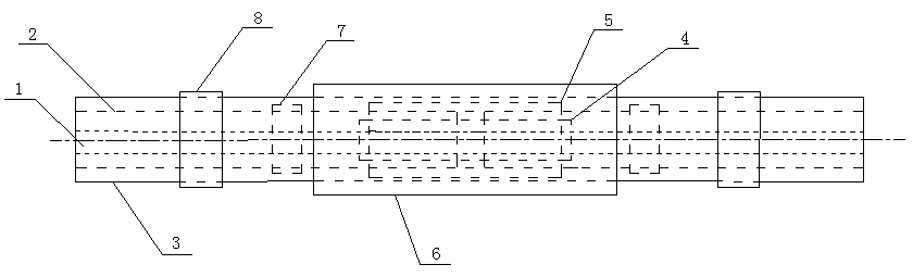
[0031] This embodiment includes a wire part, a heating part, and a ventilation part. The inside of the wire part is a cavity, and the cavity communicates with the ventilation part. The heating part is fixed on the wire part, and the heat generated by the heating part diffuses along the cavity through the ventilation part. To the entire transmission line, increase the temperature of the transmission line; two adjacent wire parts are connected by a wire splicing part to adapt to lines of different distances, and it is also easy to replace.

Embodiment 2

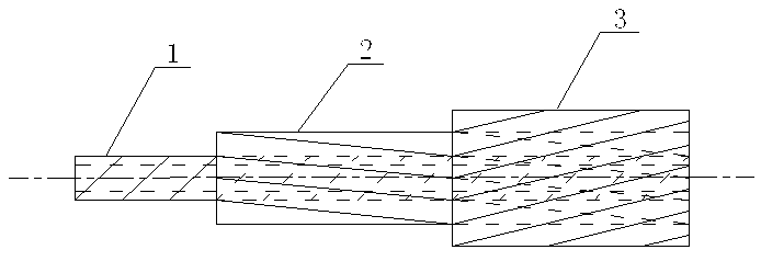
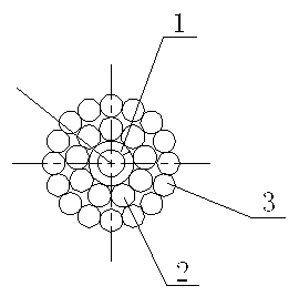
[0033] like figure 1 , figure 2 As shown, this embodiment is basically the same as Embodiment 1, the difference is that the wire part is designed as a multi-layer structure, which includes a ventilation pipe 1, a traction layer 2 and a conductive layer 3 from the inside to the outside, and the traction layer 2 is composed of several Made of steel wire spirally wound on the ventilation pipe 1, the conductive layer 3 is made of several wires wound spirally on the traction layer 2, the ventilation pipe 1 ensures good ventilation, and the traction layer 2 ensures the transmission line Good support and traction, while the conductive layer 3 ensures the basic conductivity of the transmission line, so the wire part of the structure can ensure good ventilation, support, traction and conductivity.

[0034] As a preference, the ventilation pipe 1 of the present embodiment selects a steel spiral pipe, and the spiral direction of the steel spiral pipe is opposite to the spiral direction...

Embodiment 3

[0038] like Figure 3~8 As shown, this embodiment is basically the same as Embodiment 2. The difference is that this embodiment adopts a unique design for the heating part. The heating part includes a heating element 10 and two mutually symmetrical magnetic conductors 9. There are through holes 19, the upper ends of the two magnetic conductors 9 are hinged, and the middle parts of the two magnetic conductors 9 are respectively provided with a raised magnetic conductive strip 15, and the two magnetic conductive strips 15 are in contact with each other to form a closed structure with the two magnetic conductors 9. In the loop, the two magnetizers 9 are also provided with bayonet sockets 13, and the bayonet sockets 13 are located in the closed loop formed by the two magnetizer strips 15 and the two magnetizers 9. When working, the heating element 10 and the two magnetic conductors 9 are buckled on the wire part through the through hole 19 and the bayonet 13 respectively. Through...


PUM


Abstract

The invention discloses an automatic temperature-rising power transmission line system comprising a lead wire part, a temperature rising part and a ventilation part, wherein the inner part of the lead wire part is a hollow cavity; the hollow cavity is communicated with the ventilation part; the temperature rising part is fixedly arranged on the lead wire part; the temperature rising part comprises a heating body and two magnetizers which are mutually symmetrical; the heating body is provided with a through hole; the upper ends of the two magnetizers are hinged; convex magnetism-conducting strips are respectively arranged in the middles of the two magnetizers; after the two magnetizers are mutually contacted, a closed loop is formed by the convex magnetism-conducting strips and the two magnetizers; one of the magnetism-conducting strips is wound by a coil; one end of the coil is connected with a first double-metal sheet; and the other end of the coil is connected with the heating body. With the adoption of the structure, a condition of adhering ice and snow on a power transmission line can be prevented and the condition that the pressing force borne by the power transmission line is too large so that the power transmission line shakes and even is cracked can be avoided; and therefore, the normal work of the power transmission line is guaranteed.

Description

technical field [0001] The invention relates to the field of electric power systems, in particular to an automatic heating transmission line system. Background technique [0002] With the development of our country's economy and the progress of society, electricity plays a vital role in all walks of life and people's lives. The society's demand for electricity has prompted the country to invest a lot of money in the construction of power grids, from the past high voltage to ultra-high voltage, ultra-high voltage development, from the past area power grid to the backbone power grid across several provinces, resulting in thousands of grids. Kilometers, crossing high altitude and high cold areas, especially in winter, the ice-covered wires often crush the transmission tower; the wires break, causing accidents, which seriously affect the lives of people at the back end and the normal operation of various industries. Therefore, it is very necessary to improve the snow and ice re...

Claims


Application Information

Patent Timeline
Patent Type & Authority Applications(China)
IPC IPC(8): H02G7/16H01B9/00H05B6/02
Inventor 张丽君
Owner 西昌市世通配件加工厂
Why Eureka
Try Eureka